Chapter 4: Installing the Gateway Outdoors
the receive sensitivity specification. If the power is too high, an optical attenuator is needed in the link. If the power is too low, you must trace the optical path to determine the cause of the excess loss.
Note
The
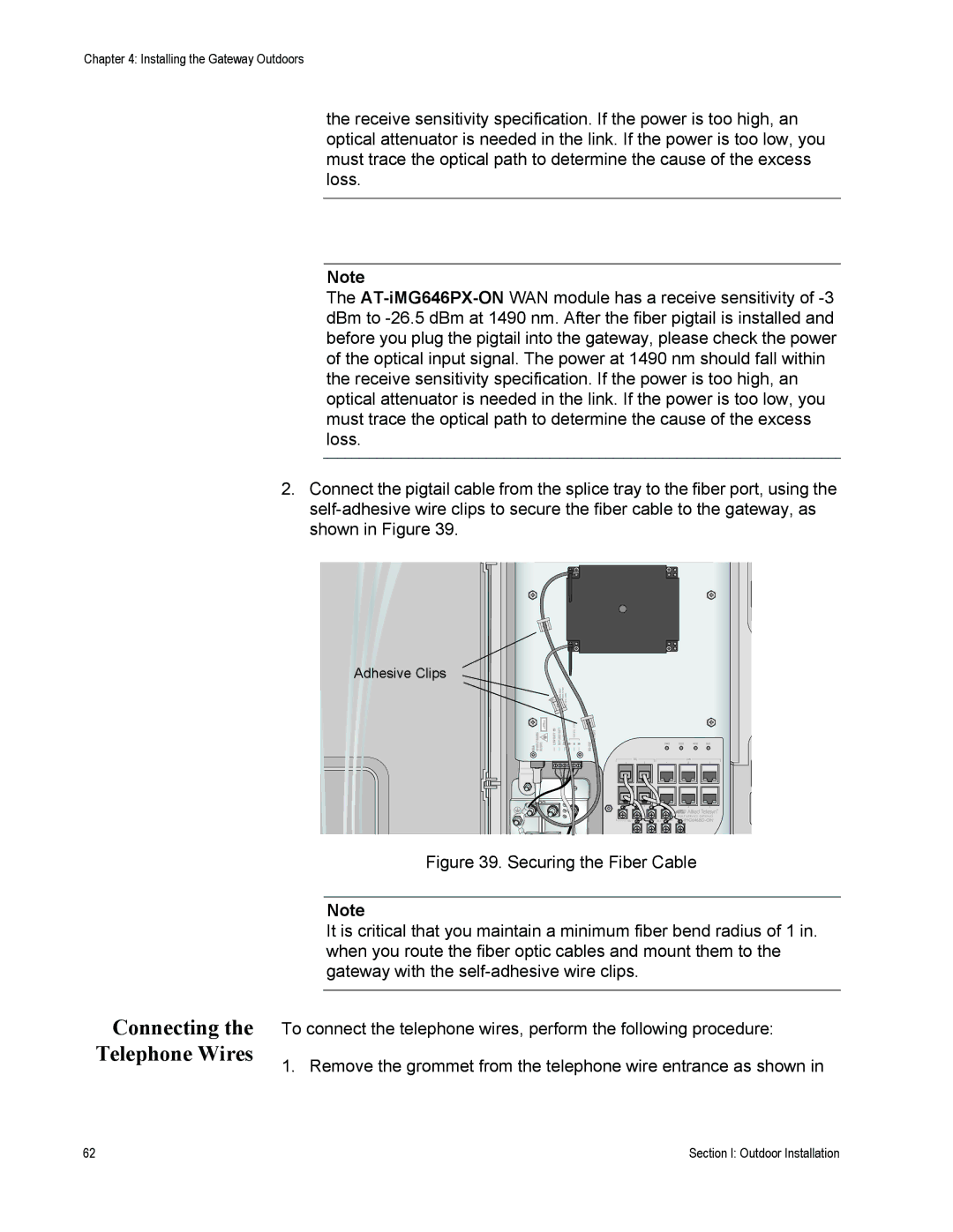
2.Connect the pigtail cable from the splice tray to the fiber port, using the
Adhesive Clips
Figure 39. Securing the Fiber Cable
Note
Connecting the Telephone Wires
It is critical that you maintain a minimum fiber bend radius of 1 in. when you route the fiber optic cables and mount them to the gateway with the
To connect the telephone wires, perform the following procedure:
1. Remove the grommet from the telephone wire entrance as shown in
62 | Section I: Outdoor Installation |
