Mounting
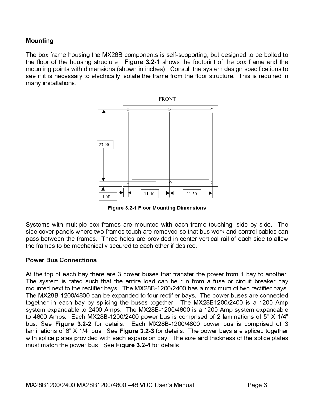
The box frame housing the MX28B components is self-supporting, but designed to be bolted to the floor of the housing structure. Figure 3.2-1shows the footprint of the box frame and the mounting points with dimensions (shown in inches). Consult the system design specifications to see if it is necessary to electrically isolate the frame from the floor structure. This is required in many installations.
Figure 3.2-1 Floor Mounting Dimensions
Systems with multiple box frames are mounted with each frame touching, side by side. The side cover panels where two frames touch are removed so that bus work and control cables can pass between the frames. Three holes are provided in center vertical rail of each side to allow the frames to be mechanically secured to each other if desired.
Power Bus Connections
At the top of each bay there are 3 power buses that transfer the power from 1 bay to another. The system is rated such that the entire load can be run from a fuse or circuit breaker bay mounted next to the rectifier bays. The MX28B-1200/2400 has a maximum of two rectifier bays. The MX28B-1200/4800 can be expanded to four rectifier bays. The power buses are connected together in each bay by splicing the buses together. The MX28B1200/2400 is a 1200 Amp system expandable to 2400 Amps. The MX28B-1200/4800 is a 1200 Amp system expandable to 4800 Amps. Each MX28B-1200/2400 power bus is comprised of 2 laminations of 5” X 1/4” bus. See Figure 3.2-2for details. Each MX28B-1200/4800 power bus is comprised of 3 laminations of 6” X 1/4” bus. See Figure 3.2-3for details. The power bays are spliced together with splice plates provided with each expansion bay. The size and thickness of the splice plates must match the power bus. See Figure 3.2-4for details.
MX28B1200/2400 MX28B1200/4800 –48 VDC User’s Manual | Page 6 |