RELAY | TERMINAL |
|
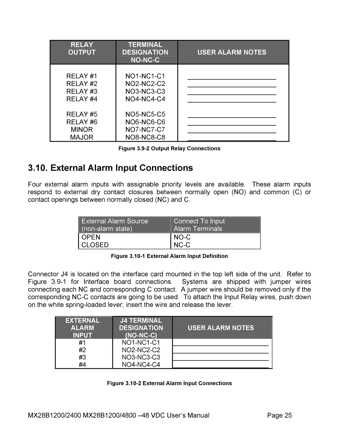
OUTPUT | DESIGNATION | USER ALARM NOTES |
|
|
|
RELAY #1 | ________________________ | |
RELAY #2 | ________________________ | |
RELAY #3 | ________________________ | |
RELAY #4 | ________________________ | |
RELAY #5 | ________________________ | |
RELAY #6 | ________________________ | |
MINOR | ________________________ | |
MAJOR | ________________________ |
Figure 3.9-2 Output Relay Connections
3.10. External Alarm Input Connections
Four external alarm inputs with assignable priority levels are available. These alarm inputs respond to external dry contact closures between normally open (NO) and common (C) or contact openings between normally closed (NC) and C.
External Alarm Source | Connect To Input |
Alarm Terminals | |
OPEN |
|
CLOSED |
|
Figure 3.10-1 External Alarm Input Definition
Connector J4 is located on the interface card mounted in the top left side of the unit. Refer to Figure
EXTERNAL
ALARM
INPUT
#1
#2
#3
#4
J4 TERMINAL DESIGNATION
USER ALARM NOTES
___________________________
___________________________
___________________________
___________________________
Figure 3.10-2 External Alarm Input Connections
MX28B1200/2400 MX28B1200/4800 | Page 25 |