Bolt-in Circuit Breaker Installation
1)Remove the circuit breaker cover panel and the plastic cover(s) from the desired location(s).
2)Install the circuit breaker(s) by bolting the circuit breaker onto the bus at the bottom of the assembly. Bolt the lug landing bus to the top of the breaker.
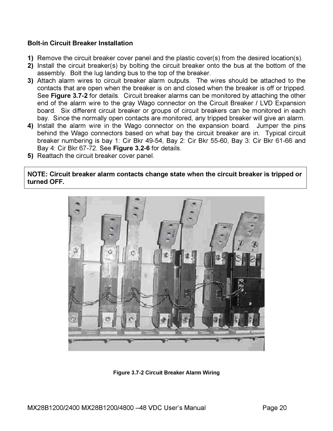
3)Attach alarm wires to circuit breaker alarm outputs. The wires should be attached to the contacts that are open when the breaker is on and closed when the breaker is off or tripped. See Figure
4)Install the alarm wire in the Wago connector on the expansion board. Jumper the pins behind the Wago connectors based on what bay the circuit breaker are in. Typical circuit breaker numbering is bay 1: Cir Bkr
5)Reattach the circuit breaker cover panel.
NOTE: Circuit breaker alarm contacts change state when the circuit breaker is tripped or turned OFF.
Figure 3.7-2 Circuit Breaker Alarm Wiring
MX28B1200/2400 MX28B1200/4800 | Page 20 |