Manuals
/
American Power Conversion
/
Computer Equipment
/
Power Supply
American Power Conversion
MX28B4800, MX28B2400 1 MX28B-1200 -48 VDC Power Plant Rectifier Bay
Models:
MX28B2400
MX28B4800
1
8
70
70
Download
70 pages
19.33 Kb
5
6
7
8
9
10
11
12
Specifications
Install
2 MX28B Block Diagram
Alarm Item
Controls and Indicators
AC Input Wiring
Warranty
Maintenance
LVD Reset
RJ45 Ethernet Connector
Page 8
Image 8
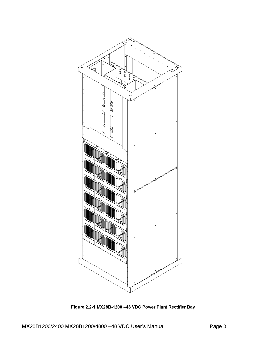
Figure
2.2-1
MX28B-1200
–48
VDC Power Plant Rectifier Bay
MX28B1200/2400 MX28B1200/4800
–48
VDC User’s Manual
Page 3
Page 7
Page 9
Page 8
Image 8
Page 7
Page 9
Contents
VDC Power Systems
Table of Contents
Commissioning and Preventive Maintenance
APC Worldwide Customer Support Limited Product Warranty
Revision History
Revision Date Description
Safety First
General Precautions
General Information
How to Use This Manual
Introduction
1 MX28B-1200 -48 VDC Power Plant Rectifier Bay
2 MX28B Block Diagram
Installation
Mechanical Installation
Unpacking Equipment
Room / Location
Power Bus Connections
Mounting
2 MX28B-1200-2400 has a maximum
Circuit Breaker/LVD Ribbon Cable Connections
5 Circuit Breaker / LVD Expansion Board
Ventilation
AC Power Connections
Fuse Alarm Ribbon Cable Connections
1 AC Input Wiring
Battery Connections
Planning the Battery Installation
Connecting the Battery Cables
1 Battery Cable Connection Locations
2 Battery Probe Connection
DC System Grounding
DC Power Output Over-Current Protection
DC Plug-in Circuit Breakers
Breaker Part Number Rating
2 Plug-in Circuit Breakers
DC Bolt-in Circuit Breakers
4 Bolt-in Circuit Breakers
Telecom Fuses
5 Telecom Fuses
Installation of Circuit Breakers and Fuses
Plug-in Circuit Breaker Installation
Bolt-in Circuit Breaker Installation
2 Circuit Breaker Alarm Wiring
Telecom Fuse Installation
GMT Fuse Installation
Load Connections
Cable Size Considerations
Circuit Breaker Connections 1 to 50 Amps
Circuit Breaker Connections 60-100 Amps
Monitoring and Relay Output Connections
GMT Fuse Connections
Front Panel DB9 Connection
Smart Cable DB9 Connection
RJ45 Ethernet Connector
Relay Output Connections
External Alarm Input Connections
NO-NC-C
Rectifier Module Installation
Commissioning and Preventive Maintenance
Electrical Installation
Battery Visual and Safety Inspection
Pre-Commissioning Inspection
Initial Set-up
AC Power Up
Commissioning
DC Power Up
Battery Power Up
Rectifier Test
LVD Test
Battery Temperature Compensation
Circuit Breaker/ Fuse Test
User Inputs
Output Relays
Final Inspection
Rectifier Management
Operation
Technical Description
System Management
System Output Capacity
System Voltage Control
System Current
Battery Management
System Status and Alarm Reporting
Battery Charging and Protection
DC Distribution
Front Panel User Interface
Controls and Indicators
Battery/Load Low Voltage Disconnect
Status Alarms System Modules Batt PIN OEM
Parameter Locations, Descriptions, and Default Values
Alarm Item
No Alarms
Address
Switzer
Batt HT Alm
Batt HT Thr
70.0 C
Batt HV Alm
Cir Bkr 1 Alm m+
Major
Cir Bkr 72 Almm+
Comp Hknee
Fuse 1 Alm
Fuse 16 Alm
Hw Batt C Almm+
Minor
LVD Reset
LVD Option
48.00
LVD Trip
Out-Rly 1 Dly m+
Sec
Out-Rly 6 Dly m+
Relay Major
Disable
Rect 1 Desc
MRF28H54
Rect 1ofN Almm+
Sys HV Alm
Sys HV Thr
Sys LT Alm
Sys LT Thr
Time
90025
SYS MS System Module SET-ALM Setup DA
Control Unit Menu Structure
V e l C o n d L e v e l I r d L e v e l U r t h L e v e l
SYS Sysin
Modrec AM Info
Modfuse LM Alias Fuse MOD Modlvd
Modlvd LM Param
Section
Alarm Outputs Output Relays
Front Panel LED Indicators
External Alarm Inputs Input Relays
Command and Monitoring Protocol
Remote Monitoring
Description
Physical Connections
Preventive Maintenance
System Visual and Safety Inspection
Equipment
Inspection
Rectifier Current Test
Test
System Voltage Test
Rectifier Alarm Test
System Temperature Test
Battery Current Test
Rectifier Current Share Test
Battery Temperature Test
Battery Preventive Maintenance Procedure
Final Inspection
Specifications
AC Input
1MRF28H54BV Rectifiers
1MRF28H54BV50 Rectifiers
VDC
Rectifiers
Power Shelf Control Unit
Compliance
Mechanical
Environmental
APC Worldwide Customer Support
US and Canada
Toll Free
Worldwide
Limited Product Warranty
Top
Page
Image
Contents