NI-3101-SIG
AMX Limited Warranty and Disclaimer
AMX Software License and Warranty Agreement
Page
Table of Contents
NetLinx Security within the Web Server
NetLinx Security with a Terminal Connection
Programming 115
Troubleshooting 143
Page
Introduction
NetLinx Integrated Master Controller Features
NI-3101-SIG Specifications
NI-3101-SIG Specifications
Front Panel Components
Rear Panel Connectors
D notation is used to represent a device number
Changing the Device Address of a NetLinx Device section on
DevicePortSystem DPS
Installation into an Equipment Rack
Number
Port
Installation and Upgrading
Program Run Disable PRD mode
Configuration Port Connections and Wiring
Working with the Configuration DIP switch
PRD Mode Settings
Port Assignments and Functionality
Modes and Front Panel LED Blink Patterns
AXlink Port and LED
Modes and LED Blink Patterns
Wiring length guidelines
Wiring Guidelines
Preparing captive wires
Wiring a power connection
Pin mini-Phoenix connector wiring diagram direct power
Using the 4-pin mini-Phoenix connector for data and power
Relay Port Connections and Wiring
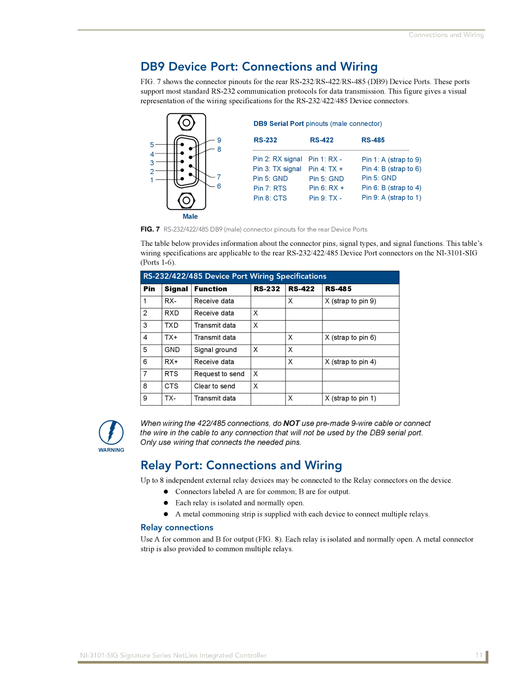
DB9 Device Port Connections and Wiring
RS-232/422/485 Device Port Wiring Specifications
Pin Signal Function RS-232 RS-422 RS-485
IR/Serial Port Connections and Wiring
Input/Output I/O Port Connections and Wiring
Port Wiring Specifications NI-3101-SIG
Function Pin
IR/Serial Connector Wiring Specifications per Port
LAN Ethernet/RJ-45 Port Connections and Wiring
LAN RJ-45 Pinouts and Signals
Connections Pairing
LAN LEDs
Replacing the Timekeeper Battery
LAN ports used by the Integrated Controllers
LAN Ports Used by the NetLinx Integrated Controllers
Connections and Wiring
Page
Communicating with the Master via the Program Port
Overview
Select Diagnostics Device Addressing from the Main menu
Setting the System Value
Device Addressing tab changing the system value
Changing the Device Address of a NetLinx Device
Using Multiple NetLinx Masters
Using the ID Button to Change the Controller’s Device Value
Recommended NetLinx Device Numbers
Axcess Devices use Axcess standards
Example Previous DS=50011
Resetting the Factory Default System and Device Values
Network Addresses dialog for a Dhcp IP Address
Obtaining the Master’s IP Address using Dhcp
Assigning a Static IP to the NetLinx Master
Configuration and Firmware Update
Communicating with the NI Device via an IP
Communications Settings dialog
TCP/IP Settings dialog
Ex 050001 NI-700
Verifying the current version of NetLinx Master Firmware
Firmware Kit File usage for NI Controllers
Upgrading the On-board Master Firmware via an IP
The Device number is always 0 for the NI Master
Upgrading the NI Controller Firmware via IP
Configuration and Firmware Update
NetLinx Security within the Web Server
NetLinx Security Terms
Accessing an Unsecured Master via an Http Address
NetLinx Security Terms
Members of that group
Browser Application Frames
Default Security Configuration
Log In/Log Out fields
Default Security Configuration case-sensitive
Master Firmware Security Access Parameters
Web Control
Managing WebControl Connections
Security Features
Manage WebControl Connection Page Features
Feature Description
Accessible by a particular user
Security Features
Security System Level Security
Communication rights, and defining the files/directories
System Level Security
Connector
If not already logged
Port. Refer to theSetting the Master’s Port
Port Communication Settings
Setting the system security options for a NetLinx Master
Icsp Authentication
Security Group Level Security
Secondary window where a user can modify the rights for
Manage Group
Either the new or existing group
Configure Group Properties
Adding a new Group
Modifying the properties of an existing Group
Deleting an existing Group
Security User Level Security
Manage Users
Properties
Configure User Properties
Configure Users Properties
Adding a new User
Case sensitive and must be unique
Deleting an existing User
Modifying the properties of an existing User
System Settings Manage System
System Settings
Manage System Page Components
Refreshing/Rebooting the Master updates this Online Tree
Each
Parent device, which may require their own firmware
Master
Manage System System Menu Buttons
System Menu Modifying the Date/Time
System Menu Changing the System Number
System Menu Controlling/Emulating Devices on the Master
System Menu Rebooting the Master
Select either the Control or Emulate option
Valid Level Data Types and Ranges
Manage System Diagnostics
Diagnostics dialog showing modify popup
Setting up and removing a Diagnostic Filter
Feature Description Update
Diagnostic Configuration Dialog
Presets
Remove
Feature Description
Setting the Master’s Port Configurations
Manage System Server
Server Submenu Options
Server Port Settings
Modifying the Server Port Settings
Port value
Address field for communication
Would be http//192.192.192.19299
Done over a more secure Https connection
Create an SSL Certificate dialog
SSL Server Certificate Creation Procedures
Server Certificate Entries
Feature Description Server Certificate Field Information
Server Creating a self-generated SSL Certificate
Server Display SSL Server Certificate Information
Server Creating a Request for an SSL Certificate
Server Regenerating an SSL Server Certificate Request
Common Steps for Requesting a Certificate from a CA
Communicating with the CA
Server Exporting an SSL Certificate Request
Export SSL Certificate dialog
Server Importing a CA created SSL Certificate
Import SSL Certificate dialog
Device Menu Configuring the LAN Settings
Network Settings Dialog
Manage System Device Menu Buttons
URL List dialog
Device Menu Developing a URL List
URL List dialog with entries
Device Menu Changing the Device Number
Device Menu Running a Diagnostic Filter
System Settings Manage License
Device Menu Controlling or Emulating a device
Device Menu Viewing the Log
Adding a new license
System Settings Manage License
System Settings Manage NetLinx Devices
Removing a license
Manage NetLinx Devices
First entry lists those NetLinx Masters which have sent out
Device Listings
NetLinx Discovery Master Announce packets NDPs
Each entry contains the data necessary to describe
Manage NetLinx Devices Binding/Unbinding Explained
Manage NetLinx Devices Displaying NDP-capable devices
Master in FIG
Manage NetLinx Devices Obtaining NetLinx Device information
Master
Manage Other Devices
Dynamic Devices provided to the Master via the NetLinx
Always be User-Defined devices
Save Settings
Administrator the capability of removing existing modules
After confirming the presence of those previously coded
Dynamic Devices within the Manage Device Bindings
PC/LAN
Internet either AMXs site or a device specified site for a
Dynamic Device Discovery Concepts
What is Dynamic Device Discovery?
Be polled for devices
Dddp
Manage Other Devices Manage Device Bindings
Configuring application-defined devices
Manage Device Bindings
What are Application Devices and their association status?
View Discovered Devices
Manage Other Devices Menu Viewing Discovered Devices
Manage Other Devices Menu Creating a new User-Defined Device
SDK-Class Types
How do I write a program that uses Dynamic Device Discovery
Hvac
VCR
How do I configure a Run-time installation
Accessing an SSL-Enabled Master via an IP Address
Security Alert and Certificate popups
Certificate Import Wizard
Using your NetLinx Master to control the G4 panel
WebControl VNC installation and Password entry screens
What to do when a Certificate Expires
Page
Initial Setup via a Terminal Connection
NetLinx Security Features
NetLinx Security Features
User has access to the Icsp communication functionality
Communications
Accessing the Security configuration options
Select to change current security option
Command Description
Option 2 Display system security options for NetLinx Master
Security Options Menu
Option 3 Add user
New password from that point forward
Option 4 Edit User
Edit User Menu
Access Rights Menu
Access Rights Menu
Option 6 Show the list of authorized users
Option 5 Delete user
Option 7 Add Group
Edit Group Menu
Path
Edit Group menu Delete directory association
Edit Group menu Display Access Rights
Edit Group menu Change Access Rights
Edit Group menu List directory associations
Option 8 Edit Group
Option 12 Display Telnet Timeout in seconds
Option 11 Set Telnet Timeout in seconds
Option 9 Delete Group
Option 10 Show List of Authorized Groups
Command
Main Security Menu
Main Security Menu
Selection saved the current security settings into flash
When changes are made to the security settings
Nent, you will be prompted to save the settings at that
These functions are only visible to administrators. If a
CommandDescription
Help menu
Help Menu Options
Size via a NetLinx program, the program command
Logging Into a Session
Logout
Help Security
Setup Security
Master SendCommands
Master SendCommands
Converting Axcess Code to NetLinx Code
Clockcommands
G4WC
~IGNOREEXTERNAL
Master IP Local Port SendCommands
Using the ID Button
Master IP Local Port SendCommands
DevicePortSystem DPS
Configuration Port Commands
Disables terminal characters echo display function
Holdoff command reveals whether the state is On or Off
Enables terminal characters echo display function
Device Holdoff Onoff command
Displays the related security commands
Displays the current LAN configuration setting
Master. MSG OFF disables the display
Extended diagnostic information messages turned on
ONDPS,channel
ONname,channel
To exit pass mode, type + + esc esc. Refer to the ESC Pass
Codes section on page 131 for more information
Releases the Dhcp setting for the Master
Reboots the Master or specified device
Master must be rebooted to acquire a new Dhcp lease
Sets the Master-to-Master route mode
DUETMEMSIZESETint should call Reboot following a set
Via a NetLinx program, the program command
Enter Y yes to approve/store the information into the Master
Subnet Mask, and Gateway IP Address
Interpreter factory default=2000, currently=600
Use caution when adjusting these values
Notification Manager factory default=2000, currently=200
Connection Manager factory default=2000, currently=500
Prompts you to enter the new time for the Master
Entering N no cancels the operation Example
Master-to-Master systems Example
Frequency to be changed or eliminate the broadcast message
Each queue Example
Displays a list of any combined devices Example
Displays a list of all devices present on the bus Example
Master logs all internal messages and keeps the most recent
Displays the log of messages stored in the Masters memory
If end is not entered, the last 20 messages will be shown
Most recent
See Show Buffers
Message buffers that were ever present on the queue
Number is Example
Desired from what device. Note the local system number is
Systems listed are in numerical order Example
Lists all active TCP/IP connections Example
Displays the current time on the Master Example
WindowsTM client programs
ESC Pass Codes
Linux Telnet client
Escape Pass Codes
LED Disable/Enable SendCommands
RS-232/422/485 SendCommands
RS232/422/485 Ports Channels
Chardm
Chard
Ctspsh
Ctspsh OFF
Rxon
Rxoff
SET Baud
Tset Baud
RS-232/422/485 SendString Escape Sequences
RS-232/422/485 SendString Escape Sequences
Xoff
XON
IR/Serial SendCommands
IR/Serial SendCommands
IR / Serial Ports Channels
IR / Serial Ports Channels
Cton
Ctof
Port 4 IR,CARRIER,IO Link
GET Mode
Iroff
POD
Ptof
PON
Pton
Meters for the IR Ports
SET IO Link
SET Mode
Short cable length 10 feet
XCH
Xchm
SendCommands
Input/Output SendCommands
GET Input
SET Input
Symptom Solution
Troubleshooting Information
Refer to the Configuration and Firmware Update section on
For more information
Refer to the Upgrading the On-board Master Firmware via an
LAN
Page
It’s Your World Take Control