Hardware Reference Guide
NXI-x000 Series
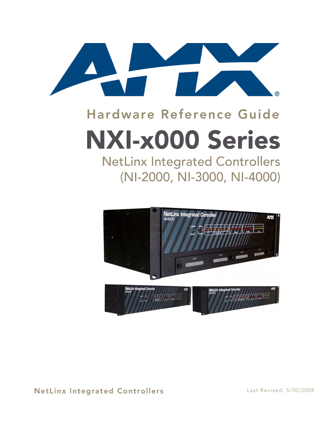
NetLinx Integrated Controllers (NI-2000, NI-3000, NI-4000)
NetLinx Integrated Controllers | Last Revised: 5/30/2008 |
Hardware Reference Guide
NetLinx Integrated Controllers | Last Revised: 5/30/2008 |