Introduction
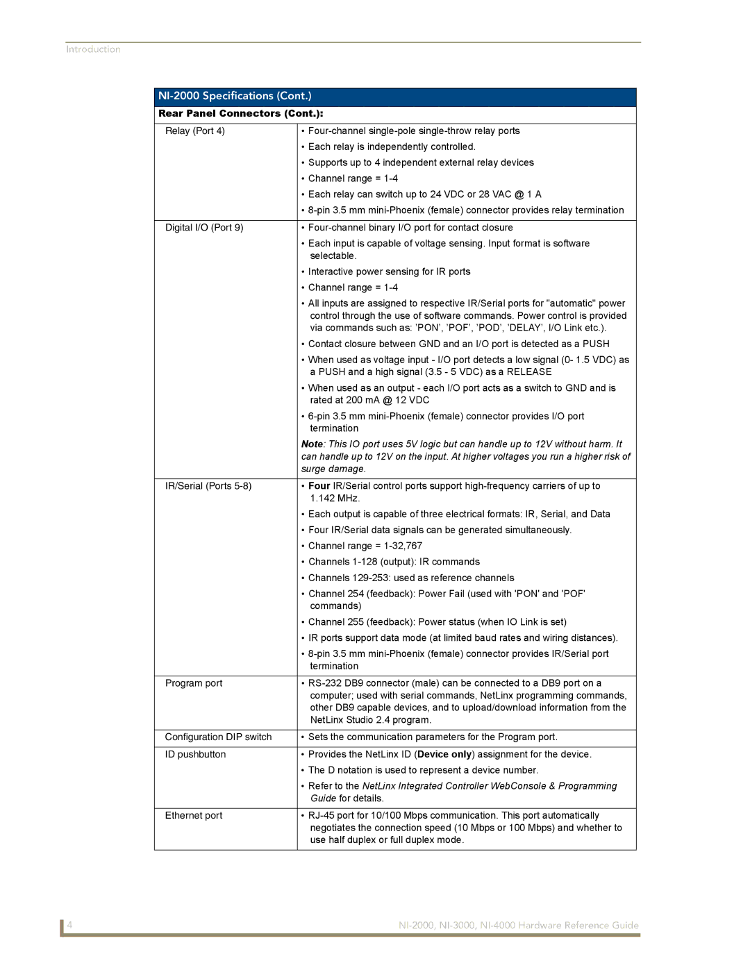
NI-2000 Specifications (Cont.)
Rear Panel Connectors (Cont.):
Relay (Port 4) | • |
| • Each relay is independently controlled. |
| • Supports up to 4 independent external relay devices |
| • Channel range = |
| • Each relay can switch up to 24 VDC or 28 VAC @ 1 A |
| • |
|
|
Digital I/O (Port 9) | • |
| • Each input is capable of voltage sensing. Input format is software |
| selectable. |
| • Interactive power sensing for IR ports |
| • Channel range = |
| • All inputs are assigned to respective IR/Serial ports for "automatic" power |
| control through the use of software commands. Power control is provided |
| via commands such as: ’PON’, ’POF’, ’POD’, ’DELAY’, I/O Link etc.). |
| • Contact closure between GND and an I/O port is detected as a PUSH |
| • When used as voltage input - I/O port detects a low signal (0- 1.5 VDC) as |
| a PUSH and a high signal (3.5 - 5 VDC) as a RELEASE |
| • When used as an output - each I/O port acts as a switch to GND and is |
| rated at 200 mA @ 12 VDC |
| • |
| termination |
| Note: This IO port uses 5V logic but can handle up to 12V without harm. It |
| can handle up to 12V on the input. At higher voltages you run a higher risk of |
| surge damage. |
|
|
IR/Serial (Ports | • Four IR/Serial control ports support |
| 1.142 MHz. |
| • Each output is capable of three electrical formats: IR, Serial, and Data |
| • Four IR/Serial data signals can be generated simultaneously. |
| • Channel range = |
| • Channels |
| • Channels |
| • Channel 254 (feedback): Power Fail (used with 'PON' and 'POF' |
| commands) |
| • Channel 255 (feedback): Power status (when IO Link is set) |
| • IR ports support data mode (at limited baud rates and wiring distances). |
| • |
| termination |
|
|
Program port | • |
| computer; used with serial commands, NetLinx programming commands, |
| other DB9 capable devices, and to upload/download information from the |
| NetLinx Studio 2.4 program. |
|
|
Configuration DIP switch | • Sets the communication parameters for the Program port. |
|
|
ID pushbutton | • Provides the NetLinx ID (Device only) assignment for the device. |
| • The D notation is used to represent a device number. |
| • Refer to the NetLinx Integrated Controller WebConsole & Programming |
| Guide for details. |
|
|
Ethernet port | • |
| negotiates the connection speed (10 Mbps or 100 Mbps) and whether to |
| use half duplex or full duplex mode. |
|
|
4 |