Connections and Wiring
Modes and Front Panel LED Blink Patterns
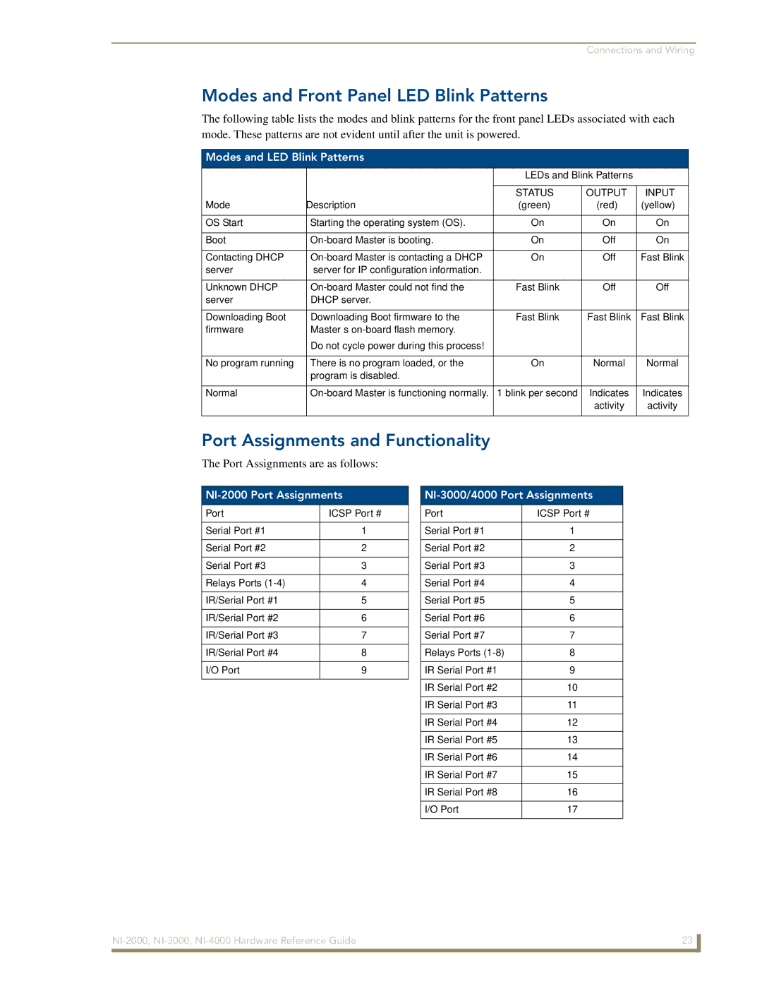
The following table lists the modes and blink patterns for the front panel LEDs associated with each mode. These patterns are not evident until after the unit is powered.
Modes and LED Blink Patterns
|
| LEDs and Blink Patterns | ||
|
|
|
|
|
|
| STATUS | OUTPUT | INPUT |
Mode | Description | (green) | (red) | (yellow) |
|
|
|
|
|
OS Start | Starting the operating system (OS). | On | On | On |
|
|
|
|
|
Boot | On | Off | On | |
|
|
|
|
|
Contacting DHCP | On | Off | Fast Blink | |
server | server for IP configuration information. |
|
|
|
|
|
|
|
|
Unknown DHCP | Fast Blink | Off | Off | |
server | DHCP server. |
|
|
|
|
|
|
|
|
Downloading Boot | Downloading Boot firmware to the | Fast Blink | Fast Blink | Fast Blink |
firmware | Master’s |
|
|
|
| Do not cycle power during this process! |
|
|
|
|
|
|
|
|
No program running | There is no program loaded, or the | On | Normal | Normal |
| program is disabled. |
|
|
|
|
|
|
|
|
Normal | 1 blink per second | Indicates | Indicates | |
|
|
| activity | activity |
|
|
|
|
|
Port Assignments and Functionality
The Port Assignments are as follows:
NI-2000 Port Assignments
Port | ICSP Port # |
|
|
Serial Port #1 | 1 |
|
|
Serial Port #2 | 2 |
|
|
Serial Port #3 | 3 |
|
|
Relays Ports | 4 |
|
|
IR/Serial Port #1 | 5 |
|
|
IR/Serial Port #2 | 6 |
|
|
IR/Serial Port #3 | 7 |
|
|
IR/Serial Port #4 | 8 |
|
|
I/O Port | 9 |
|
|
NI-3000/4000 Port Assignments
Port | ICSP Port # |
|
|
Serial Port #1 | 1 |
|
|
Serial Port #2 | 2 |
|
|
Serial Port #3 | 3 |
|
|
Serial Port #4 | 4 |
|
|
Serial Port #5 | 5 |
|
|
Serial Port #6 | 6 |
|
|
Serial Port #7 | 7 |
|
|
Relays Ports | 8 |
|
|
IR Serial Port #1 | 9 |
|
|
IR Serial Port #2 | 10 |
|
|
IR Serial Port #3 | 11 |
|
|
IR Serial Port #4 | 12 |
|
|
IR Serial Port #5 | 13 |
|
|
IR Serial Port #6 | 14 |
|
|
IR Serial Port #7 | 15 |
|
|
IR Serial Port #8 | 16 |
|
|
I/O Port | 17 |
|
|
23 | |
|
|