Connections and Wiring
Using the
To use the
To the Integrated Controller’s | PWR (+) | ||
AXlink/PWR connector | |||
|
|
| GND |
Top view |
|
|
|
GND - | AXP/TX | AXM/RX |
|
Local +12 VDC
power supply To the external AXlink device (coming from
an external power supply)
Top view
GND - | AXP/TX | AXM/RX |
FIG. 4 4-pin mini-Phoenix connector wiring diagram (using external power source)
When you connect an external power supply, do not connect the wire from the PWR terminal (coming from the external device) to the PWR terminal on the Phoenix connector attached to the Controller unit. Make sure to connect only the AXM, AXP, and GND wires to the Controller’s Phoenix connector when using an external power supply.
Make sure to connect only the GND wire on the AXlink/PWR connector when using a separate 12 VDC power supply. Do not connect the PWR wire to the AXlink connector’s PWR (+) opening.
DB9 Device Port: Connections and Wiring
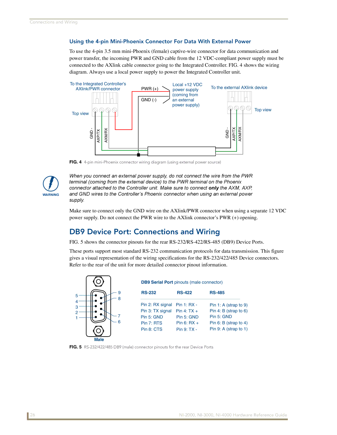
FIG. 5 shows the connector pinouts for the rear RS-232/RS-422/RS-485 (DB9) Device Ports.
These ports support most standard RS-232 communication protocols for data transmission. This figure gives a visual representation of the wiring specifications for the RS-232/422/485 Device connectors. Refer to the rear of the unit for more detailed connector pinout information.
DB9 Serial Port pinouts (male connector)
5 | 9 |
|
|
| |
8 |
|
|
| ||
4 |
|
|
| ||
| Pin 2: RX signal | Pin 1: RX - | Pin 1: A (strap to 9) | ||
3 |
| ||||
| Pin 3: TX signal | Pin 4: TX + | Pin 4: B (strap to 6) | ||
2 |
| ||||
7 | Pin 5: GND | Pin 5: GND | Pin 5: GND | ||
1 | |||||
| 6 | Pin 7: RTS | Pin 6: RX + | Pin 6: B (strap to 4) | |
|
| Pin 8: CTS | Pin 9: TX - | Pin 9: A (strap to 1) | |
| Male |
|
|
| |
FIG. 5 | |||||
26 |