Connections and Wiring
Ethernet/RJ-45 Port: Connections and Wiring
The following table lists the pinouts, signals, and pairing for the Ethernet connector.
Ethernet RJ-45 Pinouts and Signals
Pin | Signals | Connections | Pairing | Color | ||
|
|
|
|
|
|
|
1 | TX + | 1 | 1 | 1 | 2 | |
|
|
|
|
|
|
|
2 | TX - | 2 | 2 |
|
| Orange |
|
|
|
|
|
|
|
3 | RX + | 3 | 3 | 3 | 6 | |
|
|
|
|
|
|
|
4 | no connection | 4 | 4 |
|
| Blue |
|
|
|
|
|
|
|
5 | no connection | 5 | 5 |
|
| |
|
|
|
|
|
|
|
6 | RX - | 6 | 6 |
|
| Green |
|
|
|
|
|
|
|
7 | no connection | 7 | 7 |
|
| |
|
|
|
|
|
|
|
8 | no connection | 8 | 8 |
|
| Brown |
|
|
|
|
|
|
|
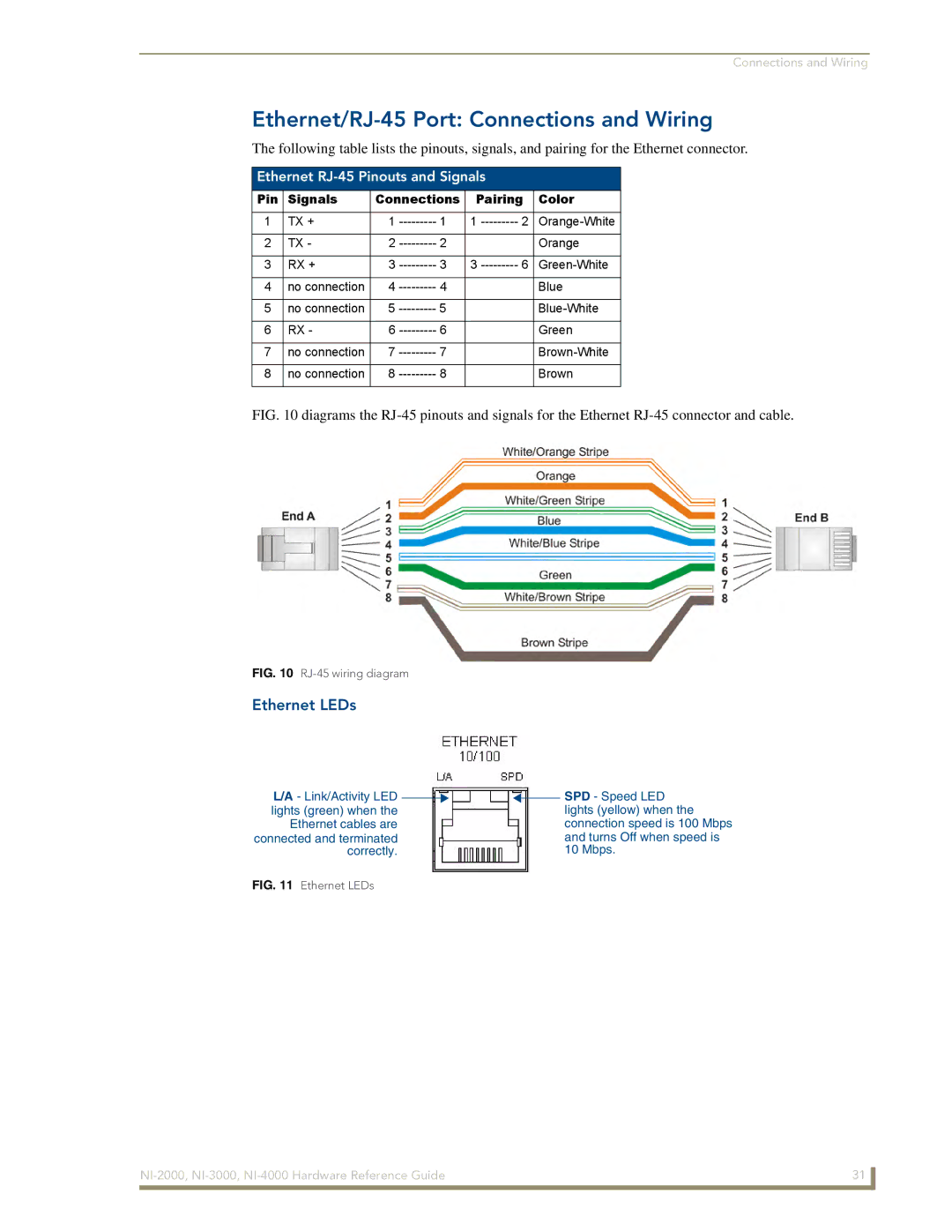
FIG. 10 diagrams the RJ-45 pinouts and signals for the Ethernet RJ-45 connector and cable.
FIG. 10 RJ-45 wiring diagram
Ethernet LEDs
L/A - Link/Activity LED ![]()
![]() lights (green) when the
lights (green) when the
Ethernet cables are connected and terminated correctly.
![]()
![]() SPD - Speed LED lights (yellow) when the connection speed is 100 Mbps and turns Off when speed is 10 Mbps.
SPD - Speed LED lights (yellow) when the connection speed is 100 Mbps and turns Off when speed is 10 Mbps.
FIG. 11 Ethernet LEDs
31 | |
|
|