NetLinx Integrated Controllers NI-2000, NI-3000, NI-4000
NXI-x000 Series
Hardware Reference Guide
NetLinx Integrated Controllers
AMX Limited Warranty and Disclaimer
Connections and Wiring
Table of Contents
Installation and Upgrading
Introduction
NetLinx Control Card Slot Connector NI-4000 only
Input/Output I/O Port Connections and Wiring
IR/Serial Port Connections and Wiring
Ethernet/RJ-45 Port Connections and Wiring
Introduction
Rear
NI-2000 Specifications
Front
Introduction
NI-2000 Specifications
Rear Panel Connectors
Front Panel Components
Introduction
NI-2000 Specifications Cont
Rear Panel Connectors Cont
surge damage
SPD speed - Yellow LED lights On when the connection speed is
NI-2000 Specifications Cont
Rear Panel Connectors Cont
Mbps and turns Off when the speed is 10 Mbps
NI-3000 Specifications
Introduction
NI-3000 Specifications
Rear Panel Connectors
Front Panel Components
Introduction
NI-3000 Specifications Cont
Rear Panel Connectors Cont
Refer to the NetLinx Integrated Controller WebConsole & Programming
Introduction
NI-3000 Specifications Cont
Rear Panel Connectors Cont
NI-2000, NI-3000, NI-4000 Hardware Reference Guide
FIG. 6 NI-4000 front and rear panel components
NI-4000 Specifications
FIG. 5 NI-4000 NetLinx Integrated Controller front view
Front Panel Components
NI-4000 Specifications
Introduction
NI-2000, NI-3000, NI-4000 Hardware Reference Guide
Introduction
NI-4000 Specifications Cont
Rear Panel Connectors
surge damage
Introduction
NI-4000 Specifications Cont
Rear Panel Connectors Cont
Refer to the NetLinx Integrated Controller WebConsole & Programming
Introduction
Related Documents
NI-4000 Specifications Cont
NI-2000, NI-3000, NI-4000 Hardware Reference Guide
Installation and Upgrading
Installing NetLinx Control Cards NI-4000 Only
Setting the NetLinx Control Card Addresses NI-4000 Only
DevicePortSystem DPS
Accessing The Internal Components On An Integrated Controller
Compact Flash Upgrades
Removing NetLinx Control Cards NI-4000 Only
The NI-2000 and NI-3000 have six screws on top and three on each side
Installation of Compact Flash Upgrades
5. Remove the upgrade card from it’s anti-static bag
Installing Into An Equipment Rack
Closing and Securing the Outer Housing
7. Apply power to the unit to complete the installation
Baud Rate Settings
Connections and Wiring
Setting the Configuration DIP Switch for the Program Port
Program Run Disable PRD Mode
Working With the Configuration DIP Switch
Setting the CardFrame DIP Switch NI-4000 Only
Program Port Connections and Wiring
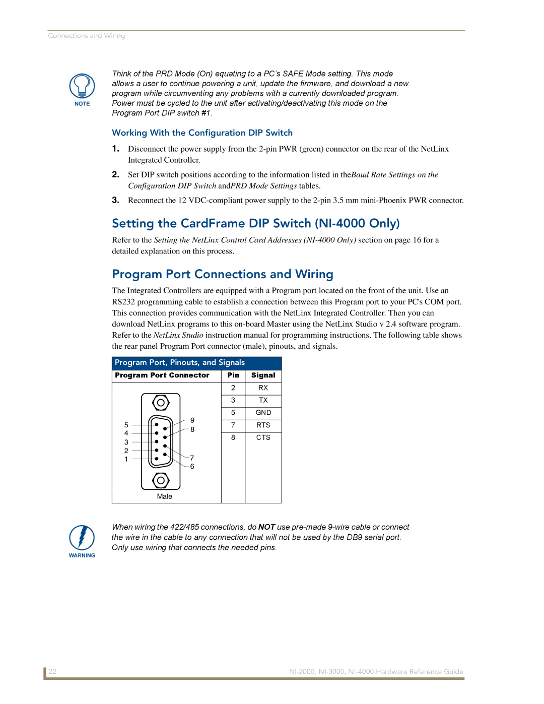
Connections and Wiring
Modes and Front Panel LED Blink Patterns
Port Assignments and Functionality
Modes and LED Blink Patterns
Wiring length guidelines
Wiring Guidelines
AXlink Port and LED
1 blink per second - Normal operation
Wiring a Power Connection
Preparing Captive Wires
1. Strip 0.25 inch 6.35 mm of insulation off all wires
Using the 4-Pin Mini-Phoenix Connector For Data and Power
DB9 Device Port Connections and Wiring
Using the 4-pin Mini-Phoenix Connector For Data With External Power
ICSNet RJ-45 Signals
ICSNet Port Connections and Wiring
RS-232/422/485 Device Port Wiring Specifications
Connections and Wiring
Relay Connections
ICSHub OUT Port Connections and Wiring
Relay Port Connections and Wiring
Input/Output I/O Port Connections and Wiring
IR/Serial Port Connections and Wiring
NetLinx Control Card Slot Connector NI-4000 only
Ethernet/RJ-45 Port Connections and Wiring
Ethernet LEDs
Ethernet Port Descriptions
Connections and Wiring
Ethernet Ports Used By the Integrated Controller
Port type
Connections and Wiring
NI-2000, NI-3000, NI-4000 Hardware Reference Guide
It’s Your World - Take Control