Introduction
NI-4000 Specifications (Cont.)
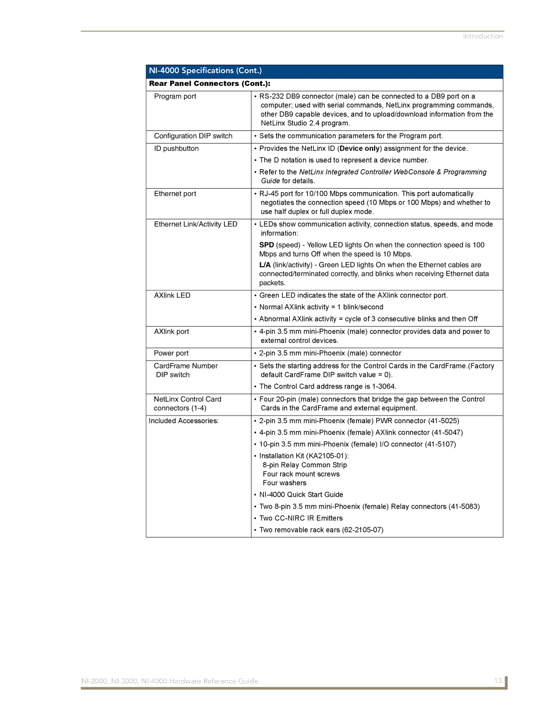
Rear Panel Connectors (Cont.):
Program port | • |
| computer; used with serial commands, NetLinx programming commands, |
| other DB9 capable devices, and to upload/download information from the |
| NetLinx Studio 2.4 program. |
|
|
Configuration DIP switch | • Sets the communication parameters for the Program port. |
|
|
ID pushbutton | • Provides the NetLinx ID (Device only) assignment for the device. |
| • The D notation is used to represent a device number. |
| • Refer to the NetLinx Integrated Controller WebConsole & Programming |
| Guide for details. |
|
|
Ethernet port | • |
| negotiates the connection speed (10 Mbps or 100 Mbps) and whether to |
| use half duplex or full duplex mode. |
|
|
Ethernet Link/Activity LED | • LEDs show communication activity, connection status, speeds, and mode |
| information: |
| SPD (speed) - Yellow LED lights On when the connection speed is 100 |
| Mbps and turns Off when the speed is 10 Mbps. |
| L/A (link/activity) - Green LED lights On when the Ethernet cables are |
| connected/terminated correctly, and blinks when receiving Ethernet data |
| packets. |
|
|
AXlink LED | • Green LED indicates the state of the AXlink connector port. |
| • Normal AXlink activity = 1 blink/second |
| • Abnormal AXlink activity = cycle of 3 consecutive blinks and then Off |
|
|
AXlink port | • |
| external control devices. |
|
|
Power port | • |
|
|
CardFrame Number | • Sets the starting address for the Control Cards in the CardFrame.(Factory |
DIP switch | default CardFrame DIP switch value = 0). |
| • The Control Card address range is |
|
|
NetLinx Control Card | • Four |
connectors | Cards in the CardFrame and external equipment. |
|
|
Included Accessories: | • |
| • |
| • |
| • Installation Kit |
| |
| Four rack mount screws |
| Four washers |
| • |
| • Two |
| • Two |
| • Two removable rack ears |
|
|
13 | |
|
|