CONNECTOR DESCRIPTIONS
The CLCI2000 Series Indexer will come with either one or two 37 Pin
|
|
|
|
|
|
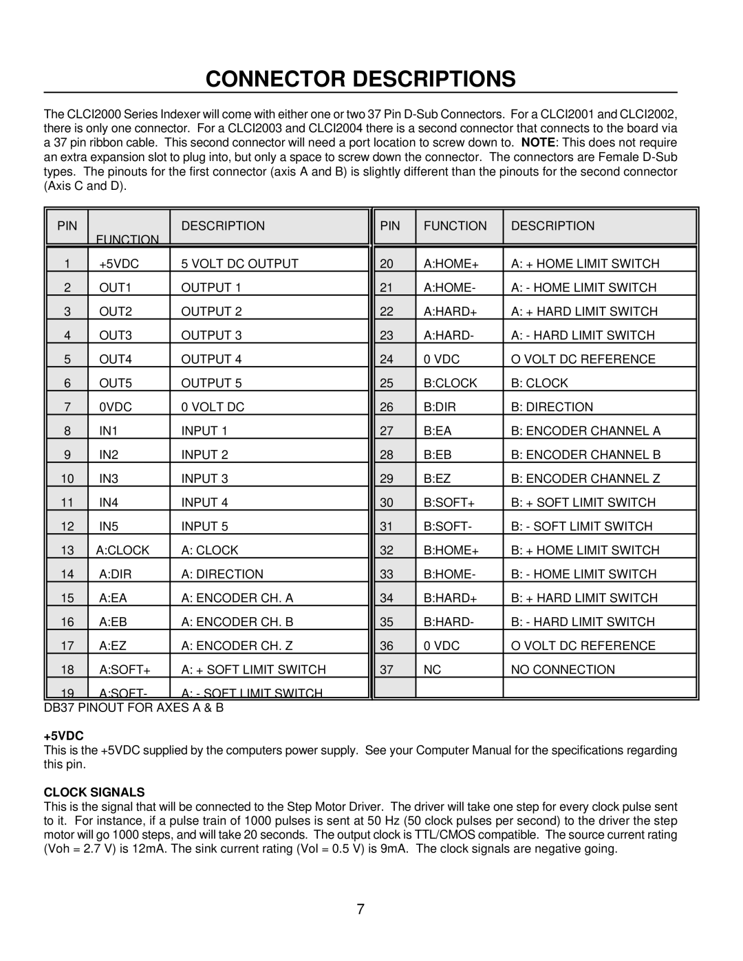
PIN |
| DESCRIPTION | PIN | FUNCTION | DESCRIPTION |
| FUNCTION |
|
|
|
|
|
|
|
|
|
|
1 | +5VDC | 5 VOLT DC OUTPUT | 20 | A:HOME+ | A: + HOME LIMIT SWITCH |
2 | OUT1 | OUTPUT 1 | 21 | A:HOME- | A: - HOME LIMIT SWITCH |
3 | OUT2 | OUTPUT 2 | 22 | A:HARD+ | A: + HARD LIMIT SWITCH |
4 | OUT3 | OUTPUT 3 | 23 | A:HARD- | A: - HARD LIMIT SWITCH |
5 | OUT4 | OUTPUT 4 | 24 | 0 VDC | O VOLT DC REFERENCE |
6 | OUT5 | OUTPUT 5 | 25 | B:CLOCK | B: CLOCK |
7 | 0VDC | 0 VOLT DC | 26 | B:DIR | B: DIRECTION |
8 | IN1 | INPUT 1 | 27 | B:EA | B: ENCODER CHANNEL A |
9 | IN2 | INPUT 2 | 28 | B:EB | B: ENCODER CHANNEL B |
10 | IN3 | INPUT 3 | 29 | B:EZ | B: ENCODER CHANNEL Z |
11 | IN4 | INPUT 4 | 30 | B:SOFT+ | B: + SOFT LIMIT SWITCH |
12 | IN5 | INPUT 5 | 31 | B:SOFT- | B: - SOFT LIMIT SWITCH |
13 | A:CLOCK | A: CLOCK | 32 | B:HOME+ | B: + HOME LIMIT SWITCH |
14 | A:DIR | A: DIRECTION | 33 | B:HOME- | B: - HOME LIMIT SWITCH |
15 | A:EA | A: ENCODER CH. A | 34 | B:HARD+ | B: + HARD LIMIT SWITCH |
16 | A:EB | A: ENCODER CH. B | 35 | B:HARD- | B: - HARD LIMIT SWITCH |
17 | A:EZ | A: ENCODER CH. Z | 36 | 0 VDC | O VOLT DC REFERENCE |
18 | A:SOFT+ | A: + SOFT LIMIT SWITCH | 37 | NC | NO CONNECTION |
19 | A:SOFT- | A: - SOFT LIMIT SWITCH |
|
|
|
|
|
|
|
|
|
DB37 PINOUT FOR AXES A & B
+5VDC
This is the +5VDC supplied by the computers power supply. See your Computer Manual for the specifications regarding this pin.
CLOCK SIGNALS
This is the signal that will be connected to the Step Motor Driver. The driver will take one step for every clock pulse sent to it. For instance, if a pulse train of 1000 pulses is sent at 50 Hz (50 clock pulses per second) to the driver the step motor will go 1000 steps, and will take 20 seconds. The output clock is TTL/CMOS compatible. The source current rating (Voh = 2.7 V) is 12mA. The sink current rating (Vol = 0.5 V) is 9mA. The clock signals are negative going.
7