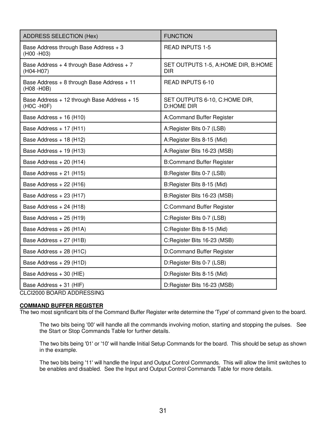
ADDRESS SELECTION (Hex) | FUNCTION |
Base Address through Base Address + 3 | READ INPUTS |
(H00 |
|
|
|
Base Address + 4 through Base Address + 7 | SET OUTPUTS |
DIR | |
|
|
Base Address + 8 through Base Address + 11 | READ INPUTS |
(H08 |
|
|
|
Base Address + 12 through Base Address + 15 | SET OUTPUTS |
(H0C | D:HOME DIR |
|
|
Base Address + 16 (H10) | A:Command Buffer Register |
|
|
Base Address + 17 (H11) | A:Register Bits |
|
|
Base Address + 18 (H12) | A:Register Bits |
|
|
Base Address + 19 (H13) | A:Register Bits |
|
|
Base Address + 20 (H14) | B:Command Buffer Register |
|
|
Base Address + 21 (H15) | B:Register Bits |
|
|
Base Address + 22 (H16) | B:Register Bits |
|
|
Base Address + 23 (H17) | B:Register Bits |
|
|
Base Address + 24 (H18) | C:Command Buffer Register |
|
|
Base Address + 25 (H19) | C:Register Bits |
|
|
Base Address + 26 (H1A) | C:Register Bits |
|
|
Base Address + 27 (H1B) | C:Register Bits |
|
|
Base Address + 28 (H1C) | D:Command Buffer Register |
|
|
Base Address + 29 (H1D) | D:Register Bits |
|
|
Base Address + 30 (HIE) | D:Register Bits |
|
|
Base Address + 31 (HIF) | D:Register Bits |
|
|
CLCI2000 BOARD ADDRESSING |
|
COMMAND BUFFER REGISTER
The two most significant bits of the Command Buffer Register write determine the 'Type' of command given to the board.
The two bits being '00' will handle all the commands involving motion, starting and stopping the pulses. See the Start or Stop Commands Table for further details.
The two bits being '01' or '10' will handle Initial Setup Commands for the board. This should be setup as shown in the example.
The two bits being '11' will handle the Input and Output Control Commands. This will allow the limit switches to be enables and disabled. See the Input and Output Control Commands Table for more details.
31