ADVANCED PROGRAMMING
In modifying an existing Library, or writing a new software library, It is strongly advised that programmers should use the current libraries for Basic or C, and transfer them to the different languages. The current libraries are 'bug free', so this will help the programmer to produce
The CLCI2000 is designed to plug into any AT/ISA PC Compatible bus. This is the bus used by most PC Manufacturers. The CLCI2000 communicates over an
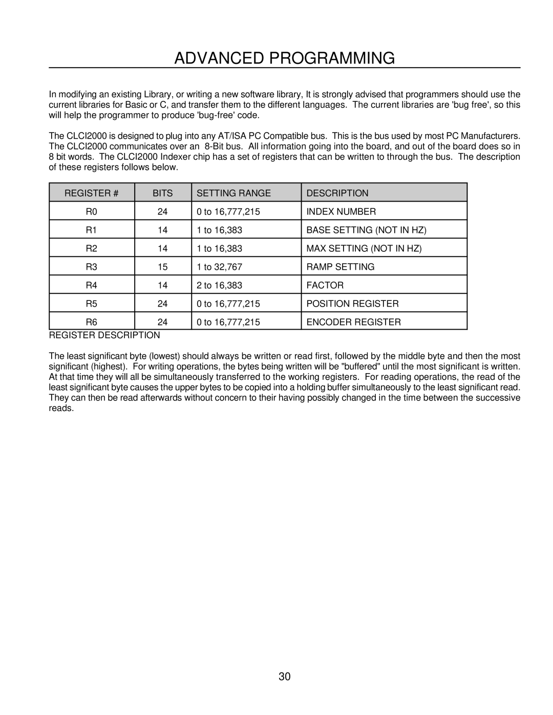
REGISTER # | BITS | SETTING RANGE | DESCRIPTION |
R0 | 24 | 0 to 16,777,215 | INDEX NUMBER |
|
|
|
|
R1 | 14 | 1 to 16,383 | BASE SETTING (NOT IN HZ) |
|
|
|
|
R2 | 14 | 1 to 16,383 | MAX SETTING (NOT IN HZ) |
|
|
|
|
R3 | 15 | 1 to 32,767 | RAMP SETTING |
|
|
|
|
R4 | 14 | 2 to 16,383 | FACTOR |
|
|
|
|
R5 | 24 | 0 to 16,777,215 | POSITION REGISTER |
|
|
|
|
R6 | 24 | 0 to 16,777,215 | ENCODER REGISTER |
|
|
|
|
REGISTER DESCRIPTION
The least significant byte (lowest) should always be written or read first, followed by the middle byte and then the most significant (highest). For writing operations, the bytes being written will be "buffered" until the most significant is written. At that time they will all be simultaneously transferred to the working registers. For reading operations, the read of the least significant byte causes the upper bytes to be copied into a holding buffer simultaneously to the least significant read. They can then be read afterwards without concern to their having possibly changed in the time between the successive reads.
30
