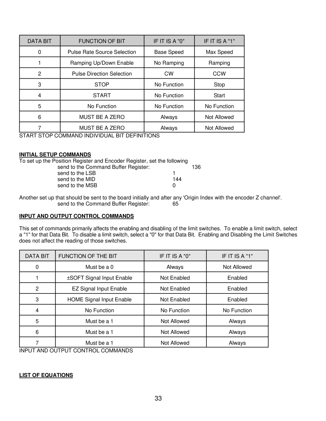
DATA BIT |
| FUNCTION OF BIT |
| IF IT IS A "0" |
| IF IT IS A "1" |
0 |
| Pulse Rate Source Selection |
| Base Speed |
| Max Speed |
|
|
|
|
|
|
|
1 |
| Ramping Up/Down Enable |
| No Ramping |
| Ramping |
|
|
|
|
|
|
|
2 |
| Pulse Direction Selection |
| CW |
| CCW |
|
|
|
|
|
|
|
3 |
| STOP |
| No Function |
| Stop |
|
|
|
|
|
|
|
4 |
| START |
| No Function |
| Start |
|
|
|
|
|
|
|
5 |
| No Function |
| No Function |
| No Function |
|
|
|
|
|
|
|
6 |
| MUST BE A ZERO |
| Always |
| Not Allowed |
|
|
|
|
|
|
|
7 |
| MUST BE A ZERO |
| Always |
| Not Allowed |
|
|
|
|
| ||
START STOP COMMAND INDIVIDUAL BIT DEFINITIONS |
|
| ||||
INITIAL SETUP COMMANDS |
|
|
| |||
To set up the Position Register and Encoder Register, set the following |
|
| ||||
| send to the Command Buffer Register: |
| 136 | |||
| send to the LSB | 1 |
|
| ||
| send to the MID | 144 |
|
| ||
| send to the MSB | 0 |
|
| ||
Another set up that should be sent to the board initially and after any 'Origin Index with the encoder Z channel'.
send to the Command Buffer Register: | 65 |
INPUT AND OUTPUT CONTROL COMMANDS
This set of commands primarily affects the enabling and disabling of the limit switches. To enable a limit switch, select a "1" for that Data Bit. To disable a limit switch, select a "0" for that Data Bit. Enabling and Disabling the Limit Switches does not affect the reading of those switches.
DATA BIT | FUNCTION OF THE BIT | IF IT IS A "0" | IF IT IS A "1" |
0 | Must be a 0 | Always | Not Allowed |
|
|
|
|
1 | ±SOFT Signal Input Enable | Not Enabled | Enabled |
|
|
|
|
2 | EZ Signal Input Enable | Not Enabled | Enabled |
|
|
|
|
3 | HOME Signal Input Enable | Not Enabled | Enabled |
|
|
|
|
4 | No Function | No Function | No Function |
|
|
|
|
5 | Must be a 1 | Not Allowed | Always |
|
|
|
|
6 | Must be a 1 | Not Allowed | Always |
|
|
|
|
7 | Must be a 1 | Not Allowed | Always |
|
|
|
|
INPUT AND OUTPUT CONTROL COMMANDS
LIST OF EQUATIONS
33