Hardware Description
3.6.4System bus signal routingThe core module is mounted onto a motherboard via the connectors HDRA and HDRB. As well as carrying all signal connections between the boards, these provide mechanical mounting (see Attaching the ARM Integrator/CM920T to a motherboard on page
The signals on the HDRA connectors are tracked between the socket on the underside and the plug on the top so that pin 1 connects to pin 1, pin 2 to pin 2 and so on. That is, the signals are routed straight through.
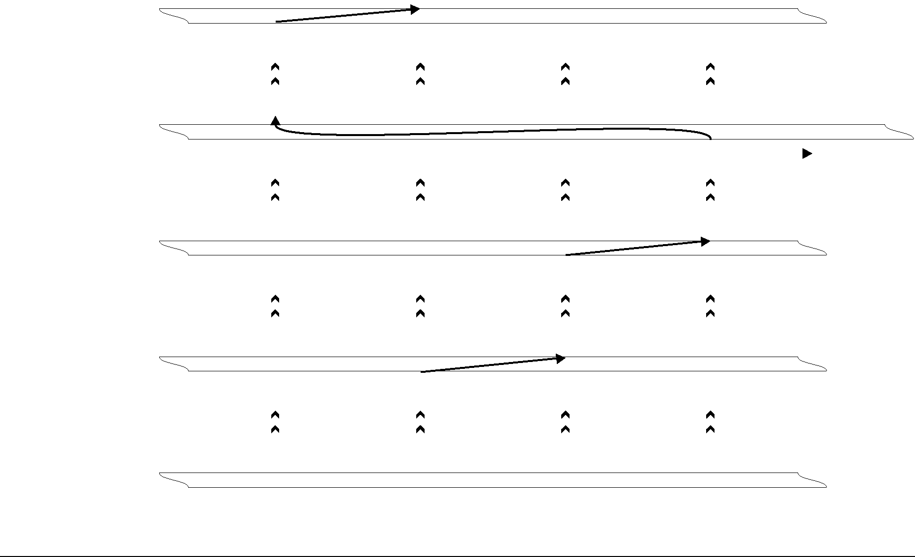
HDRBA number of signals on the HDRB connectors are rotated in groups of four between the connectors on the bottom and top of each module. This ensures that each processor (or other bus master device) on a module connects to the correct signals according to whether it is bus master 0, 1, 2, or 3. The ID for the bus master on a module is determined by the position of the module in the stack.
This signal rotation scheme is illustrated in Figure
| D |
| C |
| B |
| A |
|
| |||||
Module 3 |
|
|
|
|
|
|
|
|
|
|
|
|
|
|
| C |
|
| B |
| A |
| D |
|
| ||||
|
|
|
|
|
|
|
|
|
|
|
|
|
|
|
|
|
|
|
|
|
|
|
|
|
|
|
|
|
|
|
|
|
|
|
|
|
|
|
|
|
|
|
|
|
| C |
|
| B |
| A |
| D |
|
| ||||
Module 2 |
|
|
|
|
|
|
|
|
|
|
|
|
| To |
| B |
| A |
| D |
| C |
| ||||||
|
|
|
|
| ||||||||||
|
|
|
|
|
|
|
|
|
|
|
|
|
| devices |
|
|
|
|
|
|
|
|
|
|
|
|
| ||
|
|
|
|
|
|
|
|
|
|
|
|
|
|
|
|
|
|
|
|
|
|
|
|
|
|
|
|
|
|
| B |
| A |
| D |
| C |
|
| |||||
Module 1 |
|
|
|
|
|
|
|
|
|
|
|
|
|
|
| A |
| D |
| C |
| B |
|
| |||||
|
|
|
|
|
|
|
|
|
|
|
|
|
|
|
|
|
|
|
|
|
|
|
|
|
|
|
|
|
|
|
|
|
|
|
|
|
|
|
|
|
|
|
|
|
| A |
| D |
| C |
| B |
|
| |||||
Module 0 |
|
|
|
|
|
|
|
|
|
|
|
|
|
|
| D |
| C |
| B |
| A |
|
| |||||
|
|
|
|
|
|
|
|
|
|
|
|
|
|
|
|
|
|
|
|
|
|
|
|
|
|
|
|
|
|
|
|
|
|
|
|
|
|
|
|
|
|
|
|
|
| D |
| C |
| B |
| A |
|
| |||||
|
|
|
|
|
|
|
|
|
|
|
|
|
|
|
Motherboard
Figure
ARM DUI 0125A | © Copyright ARM Limited 1999. All rights reserved. |