Contents
Aspire T130
Service Guide
Revision History
Date Chapter Updates
Disclaimer
Copyright
Screen Messages
Conventions
Preface
Table of Contents
Table of Contents
Overview
System Specifications
CPU
Features & Specifications
Modem
Computer’s front panel consists of the following
Front Panel
Computer’s rear panel consists of the following
Rear Panel
Mainboard
Lable Component
SIS755
Block Diagram
Processor
Hardware Specifications and Configurations
Video Memory
Cache Memory
Audio Interface
Video Interface
Serial Port
IDE Interface
PCI Slot IRQ Routing Map
IRQ Assignment Map
DRQ Assignment Map
Input Voltage Variation Range
Device Standby Mode
Power Management Function Acpi support function
System Utilities
Key Function
Bios Navigation Keys
Parameter
Entering Setup
Parameter Description
Product Information
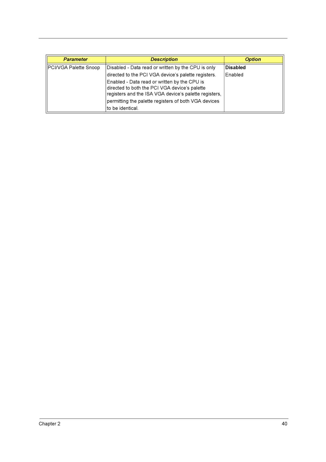
Parameter Description Option
Standard Cmos Features
All ,But keyboard
44M, 3.5
Auto
IDE Channel 0 Master/Slave and IDE Channel 1 Master/Slave
Press Enter
Advanced Bios Features
Enabled
Disabled
Fast
Hard Disk
Non-OS2
Setup
128MB
Advanced Chipset Features
800 MHz
Dram Configuration
AGP
Integrated Peripherals
Both
SiS OnChip IDE Device
SIS AC97 Audio
SiS OnChip PCI Device
378/IRQ7
Onboard SuperIO Device
3F8/IRQ4
2F8/IRQ3
ECP
SYNC+Blank
Power Management Setup
Susp, Stby Off
Former-Sts
Power Off
Delay 4 Sec
Break/Wake
Hot Key
PM Wake Up Events
PCI Pirq A-D#
PCI Device
PnP/PCI Configurations
AutoESCD
Parameter Description Option
PC Health Status
Frequency/Voltage Control
Load Default Settings
Set Supervisor/User Password
Save & Exit Setup
Exit Without Saving
Machine Disassembly and Replacement
Before You Begin
General Information
Disassemble Flow Chart
Removing the Cables
Standard Disassembly Procedure
Opening the System
Removing the Front Panel
Removing the Modem card, CD-ROM, Floppy and HDD
Removing the Power Supply
Removing the Heatsink and the CPU for T130
Removing the LED Module
Removing the Power Button
Removing the Memory
Removing the Mainboard
Removing the Daughter Board
Installing the Power Button
Standard Reassembly Procedure
Installing the Daughter Board
Installing the LED Module
Installing the Power Supply
Installing the Memory
Installing the Modem card, CD-ROM, Floppy and HDD
Installing the Cables
Closing the System
Installing the Front Panel
Troubleshooting
Power-On Self-Test Post
Checkpoint Description
Post Check Points
Is valid, take into consideration of the ESCD’s legacy infor
Checkpoint Description
Checkpoint Description
Cdrom
Checkpoint Description
Bios Messages Action/FRU
Post Error Messages List
Resource Assignments of the PnP/PCI
Diskette Drive
Error Symptom Action/FRU Processor / Processor Fan
System Board and Memory
CD/DVD-ROM Drive
Error Symptom Action/FRU
Hard Disk Drive
Video and Monitor
Real-Time Clock
Audio
Modem
Error Symptom Action/FRU
Keyboard
Error Symptom Action/FRU Parallel/Serial Ports
Power Supply
Other Problems
Before setting jumpers
Jumper and Connector Information
Header Definition
Name Connector Type Description
Jumper Type Description Settingdefault Illustrator
Jumper and Connector Settings
ATX 12V ATX 12V Power Connector
COM1
PSKBM1
USB1, USB3
COM2
AUDIO1
1394AJ2
Pin Singal Name Function Signal Name
Front Panel Connector
FRU Field Replaceable Unit List
Aspire T130 Exploded Diagram
Category Partname Description Acer P/N
Spare Parts
DVD-RW 4X DVD Supermulti DVD Super Multi DVD+/- RW DVD
Keyboard USB KBSILVER, KU0355 USB KBSILVER, KU0355, US VER
Mainboar
Model Definition and Configuration
Test Compatible Components
HDD 7200RPM
Microsoft Windows XP Home Environment Test
CPU 400MHZ
Dimm DDR
Modem
Core Mouse
LCD Monitor
LCD Monitor
Online Support Information