Cyclades-PR4000
Canadian DOC Notice
Cyclades-PR4000 Installation Manual
FCC Warning Statement
Table of Contents
IP Bridge
119
139
156
HOW to USE this Manual
Installation Assumptions
Icons
CONFIG=INTERFACE=L
Text Conventions
Convention Description
Cyclades Technical Support and Contact Information
CONFIGURATION=ALL
USA
Cyclades Corporation
What is in the BOX
With M.34 Interface
Swan Expansion Card
Slot with Swan RSV Card or DB-25 Male
Number of Phone Lines
Signaling ISDN-PRI CCS or CAS
Provisioning the T1/E1 Dialup Lines
Phone Numbers, Hunting Groups, and Hunting Sequence
Isdn Switch Type ISDN-PRI only
One-Way or Two-Way Service
Data/Voice Support
Termination at the Customer Premises
Signaling Method and Dialing Method T1 CAS-BR only
Line Coding
Framing
Using CyROS Menus
Lmi-typeANSI, Group of four, None a
Special Keys
Discard, save to Flash, or save to Run configuration
CyROS Management Utility
Cyros Management Utility
CyROS Management Utility
Slot #2 Port #26 Status
CyROS Management Utility
Operating the Front-Panel Display
LCD
Modem Order
Modem Overview
ND no
Slot/Link Order
Interface Overview Screen
Interface Overview
System Info
IP Traffic
Syslog Messages
STEP-BY-STEP Instructions for Common Applications
Example 1 Using the PR4000 as a Remote Access Server
Mask PR4000 Telephone Number
Radius
Server
Network
NAT
Step ONE
Parameter Example Your Application
IP MTU
E1/T1 Controller Menu Parameters
Radius Server Parameters
Step Three
Step Five
Step Four
Instructions for listing the configuration
192.168.0.11
192.168.0.0
Host
PR4000 Host
Parameter Example Your Application
Swan Physical Menu Parameters
Global Assigned because the IP
10 PPP Encapsulation Menu Parameters
Mlppp
Step SIX
11 Static Route Menu Parameters
Step Eight
Configuration =TO Flash Step Nine
Step Seven
Instructions for listing the configuration
Parameter Description
Configuration of the Ethernet Interface
IP Network Protocol
Incoming IP Accounting
Config =RULES LIST=IP=CONFIGURE RULES=ADD RULE=ALLOW
200.240.240.8 200.240.240.4
IP Bridge
200.240.240.9 200.240.240.3 200.240.240.2 200.240.240.1
PR4000 Link PR3000
Other Parameters
Clock Source is always External
Swan Interface
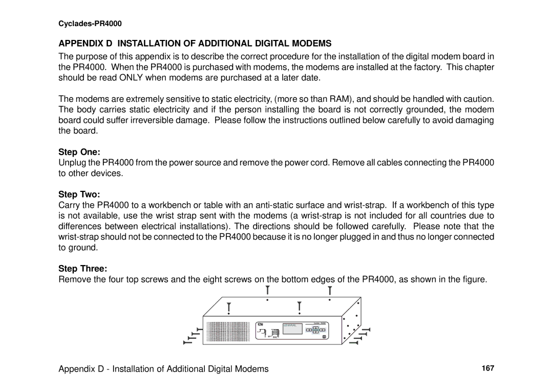
Step TWO
Protocol Be used for authentication
Rest Same as Add Group
E1 and T1 INTERFACES, Without Signaling
Otherwise, see chapter
Menu Item Description
CONFIG=INTERFACE=T1/E1=CHANNEL
Hdlc
Step Four
Controller Menu Tree
E1 and T1 INTERFACES, with Signaling
CONFIG=CONTROLLER=T1/E1
BRI Line Router Analog Line Remote Users
CCS Signaling Mode ISDN-PRI
Integrated Isdn Line
ISDN-PRI Interface Configuration Menu Tree
Timeout function
Router Analog Line Remote Users
CAS Signaling Mode
Integrated CAS Line
All Channels
Parameters Independent of Signaling Mode
Interface E1/T1 CAS One Channel
Range
Multilink Options
Channel Menu CONFIG=INTERFACE=T1/E1=CHANNEL
Modem
Internet Service Provider
IP Address
LANServer
IP Address PR4000
Router a
SIgnaling
Config Interface E1/T1 Channel
=MODEMS =DIGITAL Modem
Parameter Description
Copy From Channel
Interface T1/E1 Channel Wizards TS Profile
RAS Profile
LAN-to-LAN Profile
Ansi
Menu Items Description
12 Parameters SET by the RAS Wizard
13 Parameters SET by the LAN-TO-LAN Wizard
Network Protocol
Network Protocols
IP Protocol
Detailed Incoming IP Accounting
Transparent Bridge Protocol
PPP The Point-to-Point Protocol
DATA-LINK Protocols Encapsulation
PPP Menu
Char
Frame Relay
Pppchar
Hdlc
Parameter Description
200.1.1.1
Dlci
Salvador Recife Network
São Paulo Rio de Janeiro Network
Parameter Description
Router / DTE
Switch / DCE
Modem or
Step ONE
Menu
With PAD Packet Assembler/Disassembler
Dynamic Routing
Routing Protocols
Routing Strategies
Static Routing
10.0.0.0
Static Routes
142.10.0.0 Mask
192.168.100.0
Interfaces
Unnumbered
Add Static Route Menu Config =STATIC Routes =IP =ADD Route
RIP Configuration
Ospf
Ospf Configuration on the Interface
10Mbps, 65 for T1, 1785 for 56kbps, etc
Ospf Global Configurations
=ROUTING Protocol =OSPF =ADVERTISE this NON-OSPF Interface
CONFIG=STATIC ROUTES=IP=ADD ROUTE=OSPF Advertises this
=PASSWORD
Applies when Area Range N Status is Active
=IP=OSPF=AREA=AUTHENTICATION Type
Only when Virtual Link Status is Active
BGP-4 Configuration
255.255.255.0 200.50.50.0 PR3000 200.200.200.2 Tele Brutus
Example System with PR3000 in AS 100 Being Configured
CONFIG=IP=BGP4=BGP NETWORK=ADD
CONFIG=IP=BGP4=GLOBAL
Route Reflector Client
CONFIG=IP=BGP4=NEIGHBOR=ADD
Routing Protocols 107
Parameter Description
Route PR3000 Rred
Up Ro 100.10.0.0/16
Seq Rule Message From Tele Popeye Route Map
Routes
Routing Protocols 110
Message From Tele Popeye Rule
Seq Rule
DiscardedDiscarded RoutesRoutes
CONFIG=IP=BGP4=ROUTE MAP=ADD
CONFIG=IP=BGP4=AGGREGATE ADDRESSES=ADD
Creation of the host table
Creation of user accounts and passwords
CYROS, the Operating System
Slip
IP Accounting
Detailed information can be accessed via Snmp
PR4000 With
NAT Network Address Translation
Translated
Types of Address Translation
Menu Option Description
Interface. Five minutes is a reasonable time
NAT 122
Rules and Filters
Configuration of IP Filters
Rule List
Rules List
Bastion Host 10.0.0.0 Extension to Network
Exterior Router Perimeter Network Slot 192.168.0.0
Let Telnet Connections Out
Exterior Router
Let Mail out
Filters and Rules 127
TCP
Interior Router
Output for IP Filtering Example
Stop Telnets From the Outside Except Bastion Host
Stop Forged Packets Don’t Allow Access to News
Filters and Rules 131
Client B
Traffic Rule Lists
Link 33.33.33.1 25% or less
Filters and Rules 133
Filterlist Name traffic1
Output Showing Parameters for Traffic Rule Example
Back
Operator Start
Number Mac Address 00 60 2E 00 11
IPX Internetwork Packet Exchange
IPX Network
Internal Network
Enabling IPX
Configuring the Ethernet Interface
Configuring Other Interfaces
Parameter Value for the Example
Frame Relay
Routing
Routing Table for the Example
SAP Service Advertisement Protocol Table
Virtual Private Network Configuration
Virtual Private Network Configuration 143
IP172.16.0.0 Link
Link IP10..255.255.0
Router IP Address
RSG3 Remote IP Network 9.1 Security Gateway Router Link
Virtual Private Network Configuration 145
Virtual Private Network Configuration 146
Test CPU Boot Code step
Appendix a Troubleshooting
Event Port 2 LED Morse code
What to Do if the Router Does Not Work or Stops Working
Testing the Ethernet Interface
Testing the WAN Interface
Testing the Two T1/E1 Ports
Use of a Cross Cable for Testing T1/E1 Ports and Modems
How to Test the Modems
DPS Test Results
113
Physical Specifications
Appendix B. Hardware Specifications
General Specifications
Power Requirements
RTS DTR
External Interfaces
Console Port
Console Port
TPTX+ Tptx TPRX+ Tprx
Ethernet Port
Ethernet Port
T1/E1 Interface
T1 and E1
Straight-Through Cable
Cables
Cross Cable
Pin 13 B 10 F 15 S 17 T 24 W 11 U
DB-25 Male Cyclades Router Signal Pin PGnd
Router-MD / V.35 Cable
DB-25 to M.34 Adapter
Cross Cable for Testing the T1/E1 Ports
TxD/V.35 B TxD/V.35 a RxD/V.35 B RxD/V.35 a
Signal Pin PGnd
ISO 2110 Standard Cable
DB-25 Male Modem Cyclades Router
RJ-45 Male
E1 / DB-15 Cable
Requirements
Appendix C Configuration Without a Console
Procedure
Step Two
Appendix D Installation of Additional Digital Modems
Appendix D Installation of Additional Digital Modems
Step One
Step Five
Step Four
Step Seven
Step Six
Clamp Slot
Clamp
Step Eight
Step Nine
Step Eleven
Step Ten
Index 172
Index 173
Cyclades Philippines