50 | Connection panels |
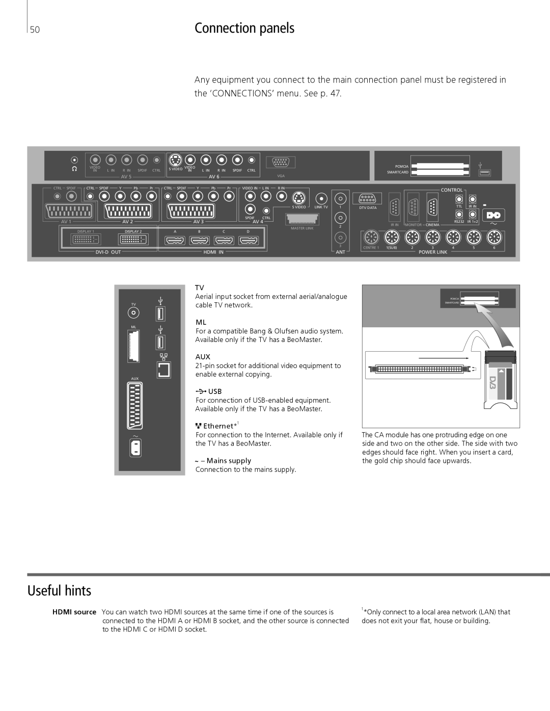
Any equipment you connect to the main connection panel must be registered in the ‘CONNECTIONS’ menu. See p. 47.
| VIDEO | R IN | SPDIF | CTRL |
| S VIDEO VIDEO | L IN | R IN | SPDIF CTRL |
|
| ||
|
|
|
| ||||||||||
|
|
|
| ||||||||||
| IN | L IN |
|
| IN |
|
| ||||||
|
|
| AV 5 |
|
|
|
|
| AV 6 | VIDEO IN |
|
| |
|
|
|
|
|
|
|
|
|
| ||||
CTRL SPDIF | CTRL | SPDIF | Y | Pb | Pr | CTRL SPDIF | Y | Pb | Pr | L IN | |||
AV 1 |
|
| AV 2 |
|
|
|
| AV 3 |
| SPDIF | CTRL | ||
|
|
|
|
|
|
| AV 4 | ||||||
DISPLAY 1 | DISPLAY 2 | A | B | C | D |
|
|
| HDMI IN |
|
VGA
R IN
S VIDEO | LINK TV | |
|
|
|
|
|
|
MASTER LINK
1
2
3
ANT
PCMCIA
SMARTCARD
|
|
| CONTROL |
|
|
DTV DATA |
|
| TTL | IR IN |
|
|
|
|
|
| |
IR IN | MONITOR | CINEMA | RS232 | IR 1+2 |
|
|
|
| |||
CENTRE 1 1(SUB) | 2 | 3 | 4 | 5 | 6 |
POWER LINK
TV
ML
AUX
TV
Aerial input socket from external aerial/analogue cable TV network.
ML
For a compatible Bang & Olufsen audio system. Available only if the TV has a BeoMaster.
AUX
![]()
![]()
![]() USB
USB
For connection of
![]()
![]()
![]() Ethernet*1
Ethernet*1
For connection to the Internet. Available only if the TV has a BeoMaster.
~– Mains supply
Connection to the mains supply.
PCMCIA |
SMARTCARD |
The CA module has one protruding edge on one side and two on the other side. The side with two edges should face right. When you insert a card, the gold chip should face upwards.
Useful hints
HDMI source You can watch two HDMI sources at the same time if one of the sources is connected to the HDMI A or HDMI B socket, and the other source is connected to the HDMI C or HDMI D socket.
1*Only connect to a local area network (LAN) that does not exit your flat, house or building.
