LOCATION AND FUNCTION OF CONTROLS
VIDEO IN (Composite video, 1x BNC connector): allows a video tape
7 recorder, video camera, color receiver/monitor, etc. having video line output to be connected to the projector.
8 | ||
for higher quality playback of Super VHS signals | ||
| ||
| connector). |
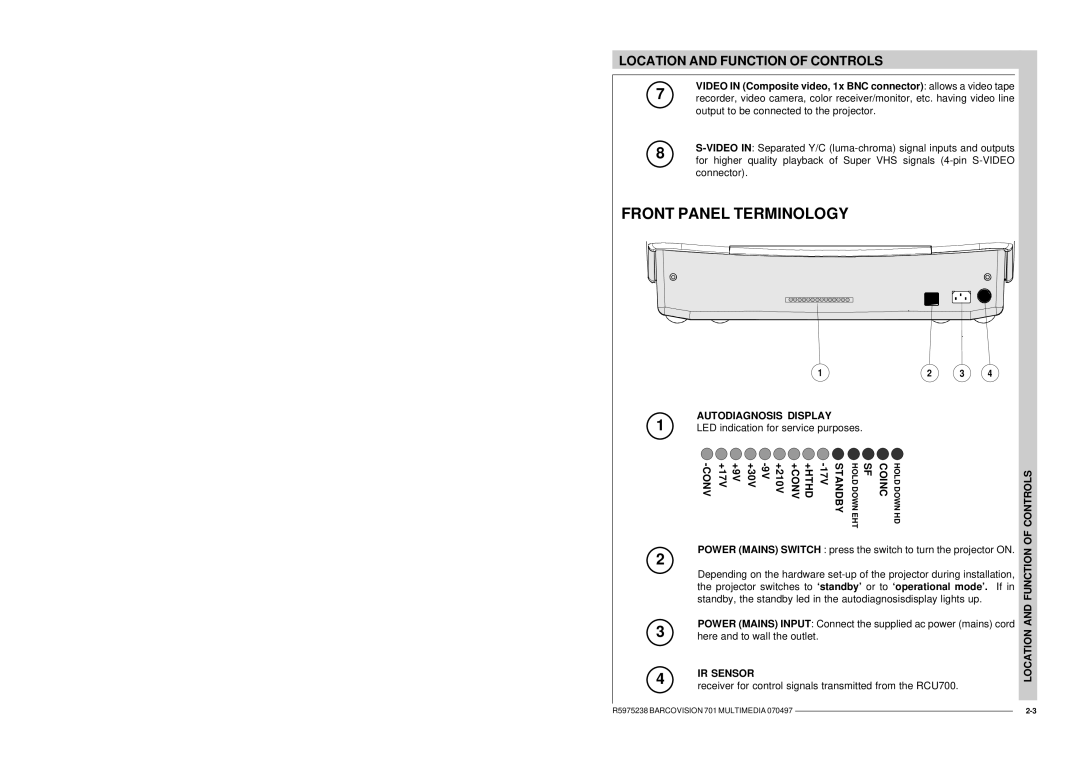
FRONT PANEL TERMINOLOGY
1 | 2 | 3 | 4 |
AUTODIAGNOSIS DISPLAY
1 LED indication for service purposes.
+9V +17V | +210V | +HTHD +CONV | STANDBY | HOLD DOWN EHT | SF | COINC | HOLD DOWN HD |
POWER (MAINS) SWITCH : press the switch to turn the projector ON.
2
Depending on the hardware
3 | POWER (MAINS) INPUT: Connect the supplied ac power (mains) cord |
here and to wall the outlet. |
4 | IR SENSOR | |
receiver for control signals transmitted from the RCU700. | ||
|
LOCATION AND FUNCTION OF CONTROLS
R5975238 BARCOVISION 701 MULTIMEDIA 070497 |
| |
| ||
|
|
|