|
|
|
|
|
|
|
|
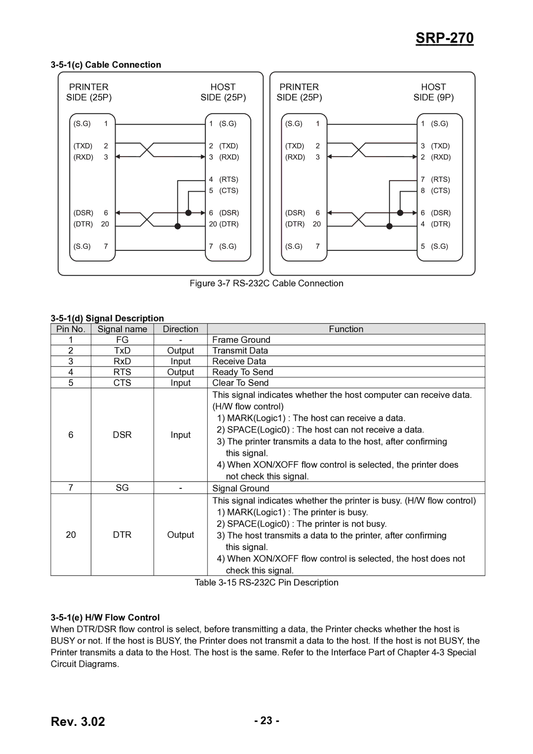
PRINTER | HOST | PRINTER | HOST |
SIDE (25P) | SIDE (25P) | SIDE (25P) | SIDE (9P) |
Figure 3-7 RS-232C Cable Connection
3-5-1(d) Signal Description
Pin No. | Signal name | Direction |
| Function | |
1 | FG | - | Frame Ground | ||
2 | TxD | Output | Transmit Data | ||
3 | RxD | Input | Receive Data | ||
4 | RTS | Output | Ready To Send | ||
5 | CTS | Input | Clear To Send | ||
|
|
| This signal indicates whether the host computer can receive data. | ||
|
|
| (H/W flow control) | ||
|
|
| 1) | MARK(Logic1) : The host can receive a data. | |
6 | DSR | Input | 2) | SPACE(Logic0) : The host can not receive a data. | |
3) | The printer transmits a data to the host, after confirming | ||||
|
|
| |||
|
|
|
| this signal. | |
|
|
| 4) | When XON/XOFF flow control is selected, the printer does | |
|
|
|
| not check this signal. | |
7 | SG | - | Signal Ground | ||
|
|
| This signal indicates whether the printer is busy. (H/W flow control) | ||
|
|
| 1) | MARK(Logic1) : The printer is busy. | |
20 | DTR | Output | 2) | SPACE(Logic0) : The printer is not busy. | |
3) | The host transmits a data to the printer, after confirming | ||||
|
|
|
| this signal. | |
|
|
| 4) | When XON/XOFF flow control is selected, the host does not | |
|
|
|
| check this signal. | |
|
| Table | |||
3-5-1(e) H/W Flow Control
When DTR/DSR flow control is select, before transmitting a data, the Printer checks whether the host is BUSY or not. If the host is BUSY, the Printer does not transmit a data to the host. If the host is not BUSY, the Printer transmits a data to the Host. The host is the same. Refer to the Interface Part of Chapter
Rev. 3.02 | - 23 - |