Name of Parts |
| Method and Procedure |
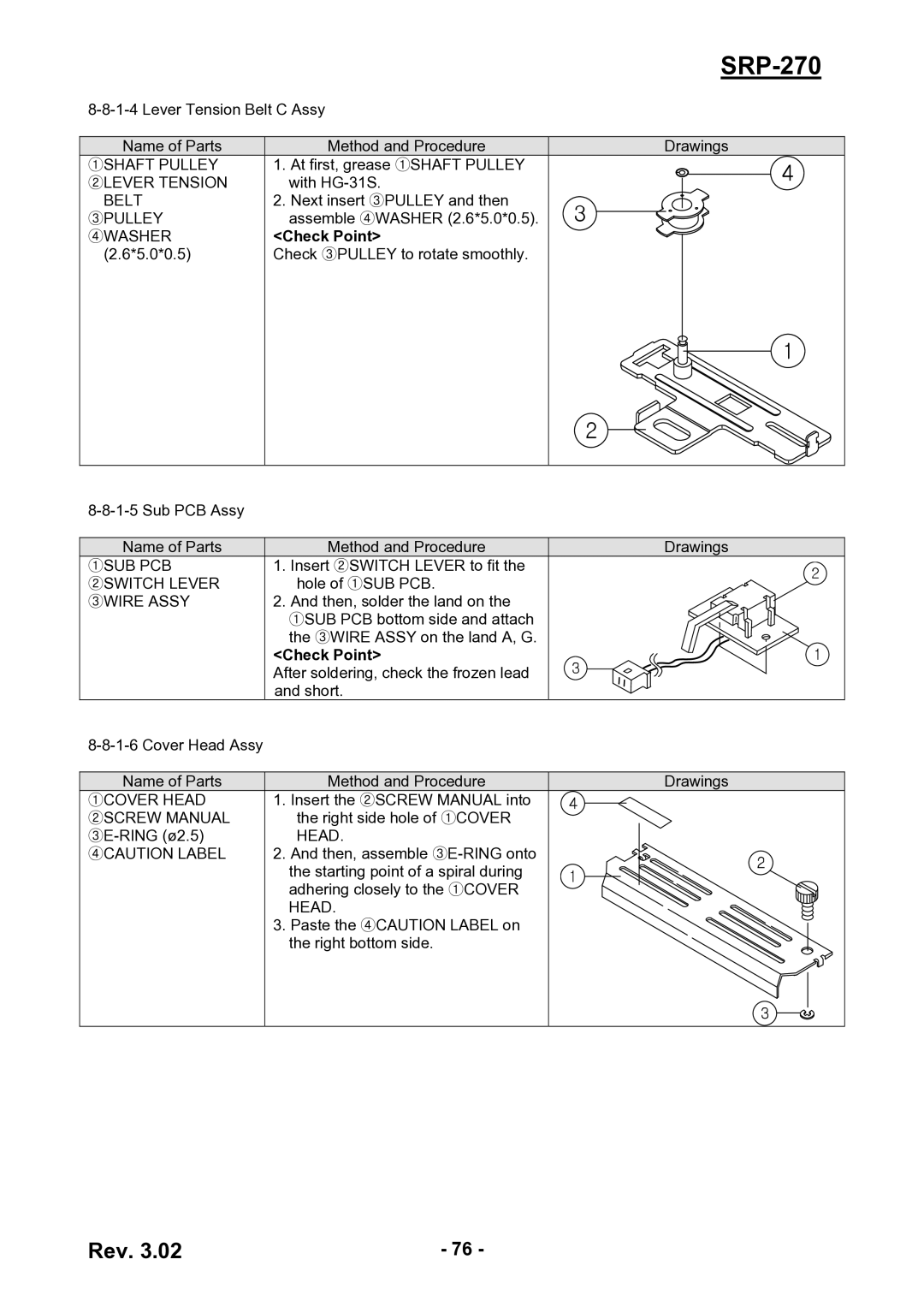
①SHAFT PULLEY | 1. | At first, grease ①SHAFT PULLEY |
②LEVER TENSION |
| with |
BELT | 2. | Next insert ③PULLEY and then |
③PULLEY |
| assemble ④WASHER (2.6*5.0*0.5). |
④WASHER | <Check Point> | |
(2.6*5.0*0.5) | Check ③PULLEY to rotate smoothly. | |
|
|
|
Name of Parts | Method and Procedure |
①SUB PCB | 1. Insert ②SWITCH LEVER to fit the |
②SWITCH LEVER | hole of ①SUB PCB. |
③WIRE ASSY | 2. And then, solder the land on the |
| ①SUB PCB bottom side and attach |
| the ③WIRE ASSY on the land A, G. |
| <Check Point> |
| After soldering, check the frozen lead |
| and short. |
| |
|
|
Name of Parts | Method and Procedure |
①COVER HEAD | 1. Insert the ②SCREW MANUAL into |
②SCREW MANUAL | the right side hole of ①COVER |
HEAD. | |
④CAUTION LABEL | 2. And then, assemble |
| the starting point of a spiral during |
| adhering closely to the ①COVER |
| HEAD. |
| 3. Paste the ④CAUTION LABEL on |
| the right bottom side. |
|
|
SRP-270
Drawings
Drawings
Drawings
Rev. 3.02 | - 76 - |