|
|
|
|
|
|
|
|
|
|
| |
|
|
|
|
|
|
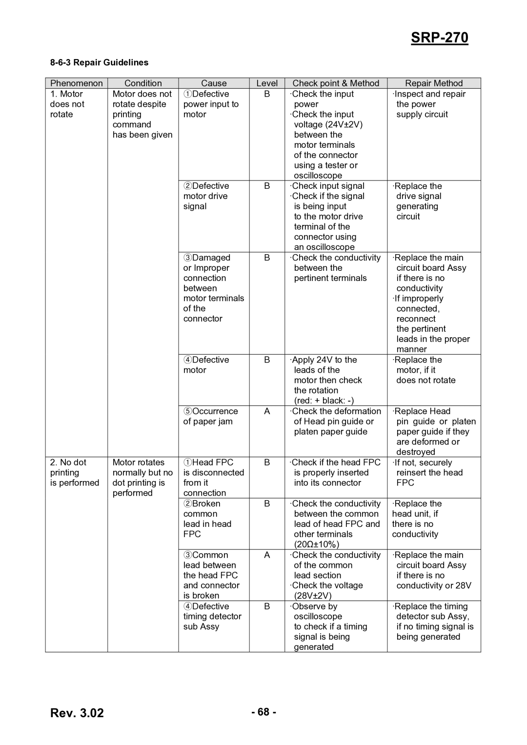
Phenomenon | Condition | Cause | Level | Check point & Method | Repair Method |
1. Motor | Motor does not | ①Defective | B | ·Check the input | ·Inspect and repair |
does not | rotate despite | power input to |
| power | the power |
rotate | printing | motor |
| ·Check the input | supply circuit |
| command |
|
| voltage (24V±2V) |
|
| has been given |
|
| between the |
|
|
|
|
| motor terminals |
|
|
|
|
| of the connector |
|
|
|
|
| using a tester or |
|
|
|
|
| oscilloscope |
|
|
| ②Defective | B | ·Check input signal | ·Replace the |
|
| motor drive |
| ·Check if the signal | drive signal |
|
| signal |
| is being input | generating |
|
|
|
| to the motor drive | circuit |
|
|
|
| terminal of the |
|
|
|
|
| connector using |
|
|
|
|
| an oscilloscope |
|
|
| ③Damaged | B | ·Check the conductivity | ·Replace the main |
|
| or Improper |
| between the | circuit board Assy |
|
| connection |
| pertinent terminals | if there is no |
|
| between |
|
| conductivity |
|
| motor terminals |
|
| ·If improperly |
|
| of the |
|
| connected, |
|
| connector |
|
| reconnect |
|
|
|
|
| the pertinent |
|
|
|
|
| leads in the proper |
|
|
|
|
| manner |
|
| ④Defective | B | ·Apply 24V to the | ·Replace the |
|
| motor |
| leads of the | motor, if it |
|
|
|
| motor then check | does not rotate |
|
|
|
| the rotation |
|
|
|
|
| (red: + black: |
|
|
| ⑤Occurrence | A | ·Check the deformation | ·Replace Head |
|
| of paper jam |
| of Head pin guide or | pin guide or platen |
|
|
|
| platen paper guide | paper guide if they |
|
|
|
|
| are deformed or |
|
|
|
|
| destroyed |
2. No dot | Motor rotates | ①Head FPC | B | ·Check if the head FPC | ·If not, securely |
printing | normally but no | is disconnected |
| is properly inserted | reinsert the head |
is performed | dot printing is | from it |
| into its connector | FPC |
| performed | connection |
|
|
|
|
| ②Broken | B | ·Check the conductivity | ·Replace the |
|
| common |
| between the common | head unit, if |
|
| lead in head |
| lead of head FPC and | there is no |
|
| FPC |
| other terminals | conductivity |
|
|
|
| (20Ω±10%) |
|
|
| ③Common | A | ·Check the conductivity | ·Replace the main |
|
| lead between |
| of the common | circuit board Assy |
|
| the head FPC |
| lead section | if there is no |
|
| and connector |
| ·Check the voltage | conductivity or 28V |
|
| is broken |
| (28V±2V) |
|
|
| ④Defective | B | ·Observe by | ·Replace the timing |
|
| timing detector |
| oscilloscope | detector sub Assy, |
|
| sub Assy |
| to check if a timing | if no timing signal is |
|
|
|
| signal is being | being generated |
|
|
|
| generated |
|
Rev. 3.02 | - 68 - |