SRP-270
[ Description of Timing chart.2 ]
⑬When head carriage step motor stops(left → left)
⑭The start position of head carriage step motor from right to left
⑮ When first outing of head pin from right to left
ⓐ When last outing of head pin from right to left and when starting line feed ⓑ When ending of printing from fight to left
ⓒ The start position of second printing from left to right
ⓓ Solenoid on time(unlocking
ⓔ When head carriage tip covers the home sensor (after printing from right to left)
*Electrical Circuit Operation Principles (Hardware Configuration)
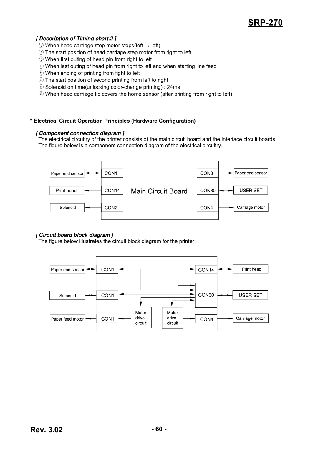
[ Component connection diagram ]
The electrical circuitry of the printer consists of the main circuit board and the interface circuit boards. The figure below is a component connection diagram of the electrical circuitry.
[ Circuit board block diagram ]
The figure below illustrates the circuit block diagram for the printer.
Rev. 3.02 | - 60 - |