SRP-270

4-3-9 DIP Switch Circuit

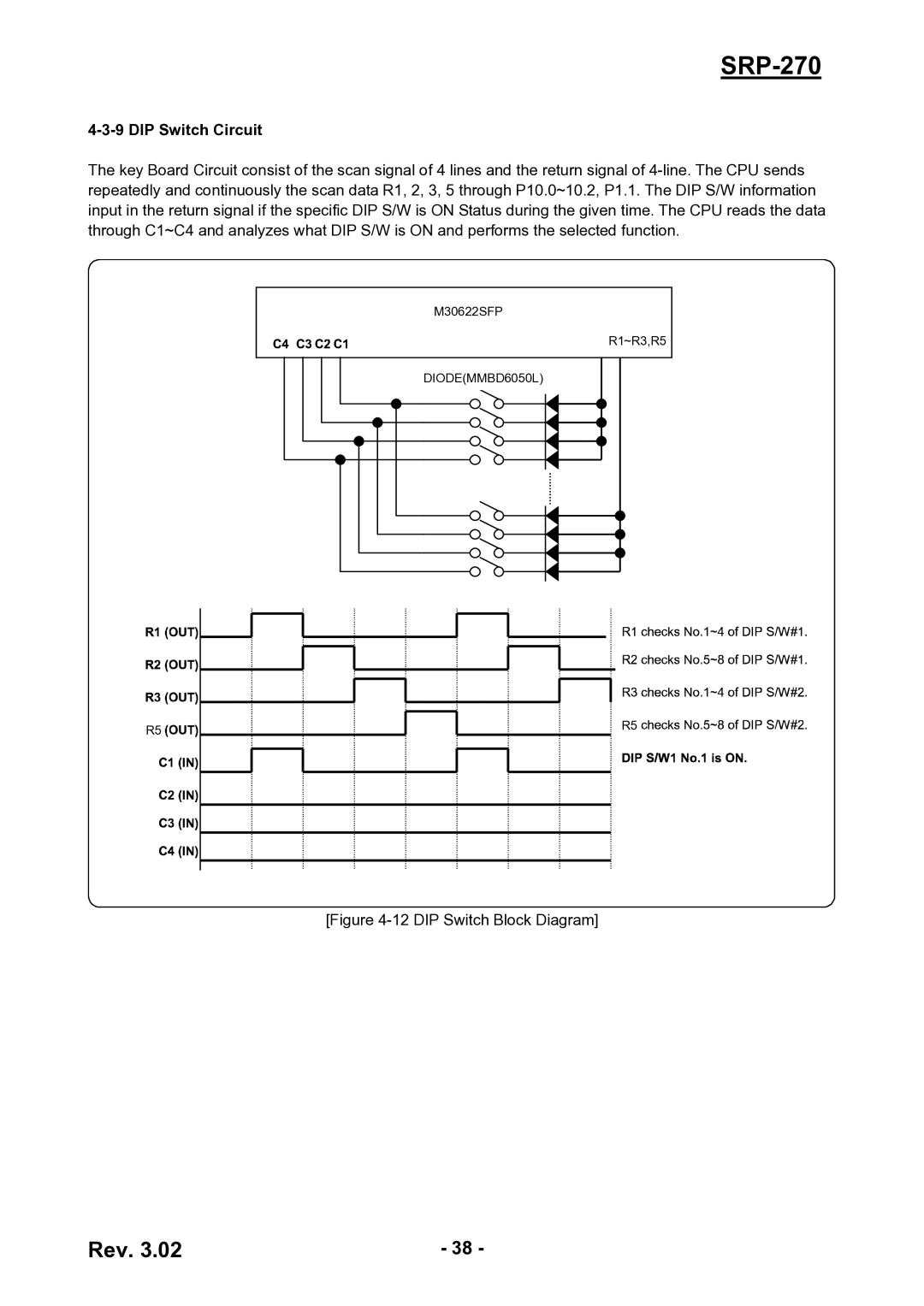
The key Board Circuit consist of the scan signal of 4 lines and the return signal of 4-line. The CPU sends repeatedly and continuously the scan data R1, 2, 3, 5 through P10.0~10.2, P1.1. The DIP S/W information input in the return signal if the specific DIP S/W is ON Status during the given time. The CPU reads the data through C1~C4 and analyzes what DIP S/W is ON and performs the selected function.

M30622SFP

R1~R3,R5

DIODE(MMBD6050L)

R5

R5

[Figure 4-12 DIP Switch Block Diagram]

Rev. 3.02

- 38 -

Page 38
Image 38
BIXOLON SRP-270 service manual DIP Switch Circuit, DIP Switch Block Diagram