SRP-270
8-8-3 Adjustment
When assembling this printer, be sure to refer to the required adjustment procedure.
To ensure normal operation of the printer after disassembly or replacement of a Component for maintenance or repair. Be sure to perform along to the required method.
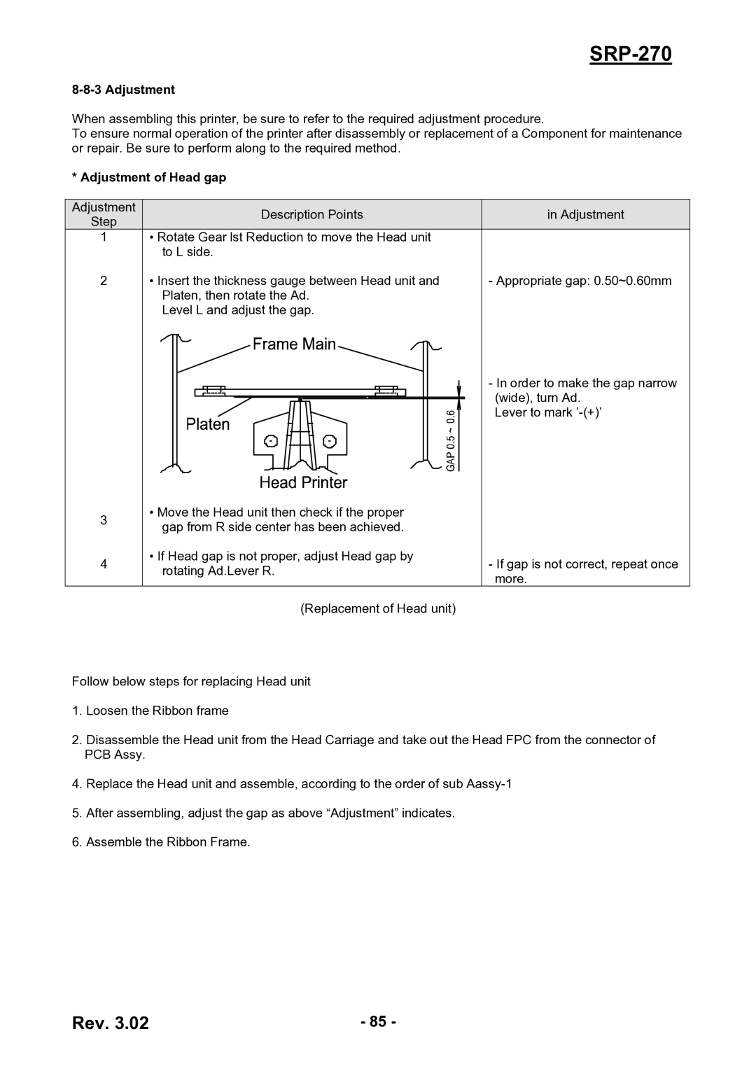
* Adjustment of Head gap
Adjustment | Description Points | in Adjustment | |
Step | |||
|
|
1• Rotate Gear lst Reduction to move the Head unit to L side.
2 | • Insert the thickness gauge between Head unit and | - Appropriate gap: 0.50~0.60mm |
| Platen, then rotate the Ad. |
|
| Level L and adjust the gap. |
|
- In order to make the gap narrow (wide), turn Ad.
Lever to mark
•Move the Head unit then check if the proper
3 gap from R side center has been achieved.
4 | • If Head gap is not proper, adjust Head gap by | - If gap is not correct, repeat once | |
rotating Ad.Lever R. | |||
| more. | ||
|
| ||
| (Replacement of Head unit) |
|
Follow below steps for replacing Head unit
1.Loosen the Ribbon frame
2.Disassemble the Head unit from the Head Carriage and take out the Head FPC from the connector of PCB Assy.
4.Replace the Head unit and assemble, according to the order of sub
5.After assembling, adjust the gap as above “Adjustment” indicates.
6.Assemble the Ribbon Frame.
Rev. 3.02 | - 85 - |