|
|
|
|
|
|
|
|
|
|
|
|
|
|
|
| ||||
|
|
|
|
|
|
|
|
|
|
| Name of Parts |
|
|
|
| Method and Procedure | |||
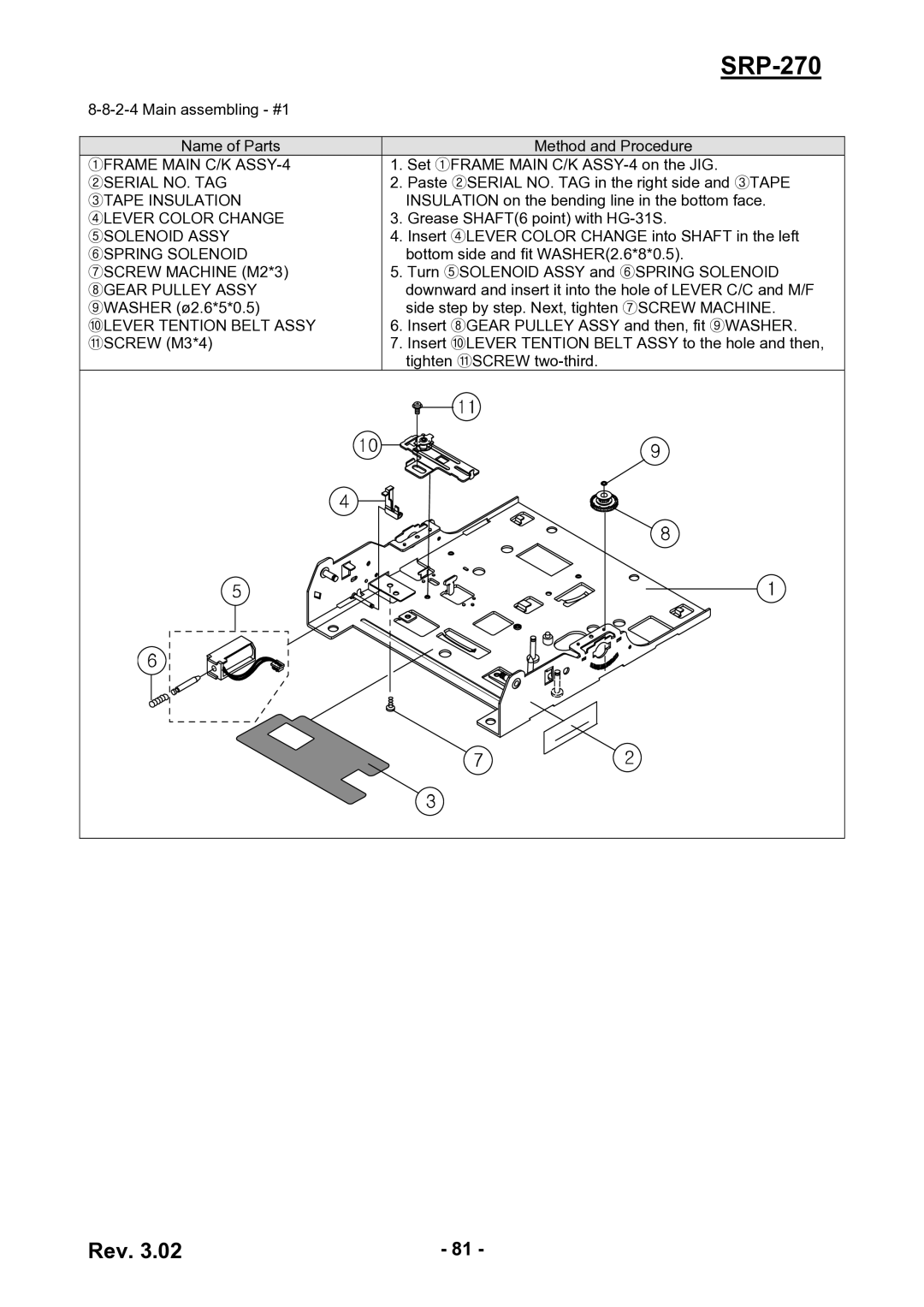
①FRAME MAIN C/K |
| 1. Set ①FRAME MAIN C/K | |||||||
②SERIAL NO. TAG |
| 2. Paste ②SERIAL NO. TAG in the right side and ③TAPE | |||||||
③TAPE INSULATION |
|
| INSULATION on the bending line in the bottom face. | ||||||
④LEVER COLOR CHANGE |
| 3. Grease SHAFT(6 point) with | |||||||
⑤SOLENOID ASSY |
| 4. Insert ④LEVER COLOR CHANGE into SHAFT in the left | |||||||
⑥SPRING SOLENOID |
|
| bottom side and fit WASHER(2.6*8*0.5). | ||||||
⑦SCREW MACHINE (M2*3) |
| 5. Turn ⑤SOLENOID ASSY and ⑥SPRING SOLENOID | |||||||
⑧GEAR PULLEY ASSY |
|
| downward and insert it into the hole of LEVER C/C and M/F | ||||||
⑨WASHER (ø2.6*5*0.5) |
|
| side step by step. Next, tighten ⑦SCREW MACHINE. | ||||||
⑩LEVER TENTION BELT ASSY |
| 6. Insert ⑧GEAR PULLEY ASSY and then, fit ⑨WASHER. | |||||||
⑪SCREW (M3*4) |
| 7. Insert ⑩LEVER TENTION BELT ASSY to the hole and then, | |||||||
|
|
|
|
|
| tighten ⑪SCREW | |||
|
|
|
|
|
|
|
|
|
|
|
|
|
|
|
|
|
|
|
|
|
|
|
|
|
|
|
|
|
|
|
|
|
|
|
|
|
|
|
|
|
|
|
|
|
|
|
|
|
|
|
|
|
|
|
|
|
|
|
|
|
|
|
|
|
|
|
|
|
|
|
|
|
|
|
|
|
|
|
|
Rev. 3.02 | - 81 - |