8-8-1 Sub-assemblies
Name of Parts | Method and Procedure |
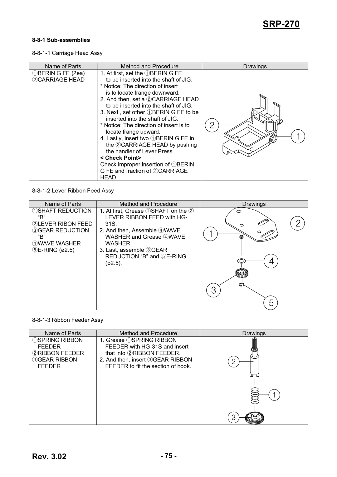
①BERIN G FE (2ea) | 1. At first, set the ①BERIN G FE |
②CARRIAGE HEAD | to be inserted into the shaft of JIG. |
| * Notice: The direction of insert |
| is to locate frange downward. |
| 2. And then, set a ②CARRIAGE HEAD |
| to be inserted into the shaft of JIG. |
| 3. Next , set other ①BERIN G FE to be |
| inserted into the shaft of JIG. |
| * Notice: The direction of insert is to |
| locate frange upward. |
| 4. Lastly, insert two ①BERIN G FE in |
| the ②CARRIAGE HEAD by pushing |
| the handler of Lever Press. |
| < Check Point> |
| Check improper insertion of ①BERIN |
| G FE and fraction of ②CARRIAGE |
| HEAD. |
Name of Parts | Method and Procedure |
①SHAFT REDUCTION | 1. At first, Grease ①SHAFT on the ② |
“B” | LEVER RIBBON FEED with HG- |
②LEVER RIBON FEED | 31S. |
③GEAR REDUCTION | 2. And then, Assemble ④WAVE |
“B” | WASHER and Grease ④WAVE |
④WAVE WASHER | WASHER. |
3. Last, assemble ③GEAR | |
| REDUCTION “B” and |
| (ø2.5). |
|
|
SRP-270
Drawings
Drawings
Name of Parts | Method and Procedure |
①SPRING RIBBON | 1. Grease ①SPRING RIBBON |
FEEDER | FEEDER with |
②RIBBON FEEDER | that into ②RIBBON FEEDER. |
③GEAR RIBBON | 2. And then, insert ③GEAR RIBBON |
FEEDER | FEEDER to fit the section of hook. |
|
|
Drawings
Rev. 3.02 | - 75 - |
