Name of Parts
①AD LEVER
②SHAFT HEAD GUIDE
③SHAFT HEAD CARRIAGE
⑤HEAD PRINT
⑥SCREW (M3*10, 2EA)
⑦BRACKET HEAD COVER “L”
⑧BRACKET HEAD COVER “R”
⑨SCREW MACHINE (M2.6*3, 2EA)
SRP-270
Method and Procedure
1.Set FRAME MAIN on the JIG.
2.Insert ①AD LEVER in the left side and then, turn to the downward. Next insert the other ①AD LEVER into ②SHAFT HEAD GUIDE and insert the Sub Assy into F/M from right to left and then, turn AD LEVER downward.
3.Insert ③SHAFT HEAD CARRIAGE from left to right and fit
4.Insert FPC into ⑤HEAD PRINT and set HEAD Assy to CARRIAGE HEAD, and then tighten two ⑥SCREW.
5.Tighten the screw mounted to LEVER TENTION BELT ASSY completely.
6.Fit ⑦BRACKET HEAD COVER "L" and ⑧BRACKET HEAD COVER "R" to both boss and then tighten two ⑨SCREW MACHINE.
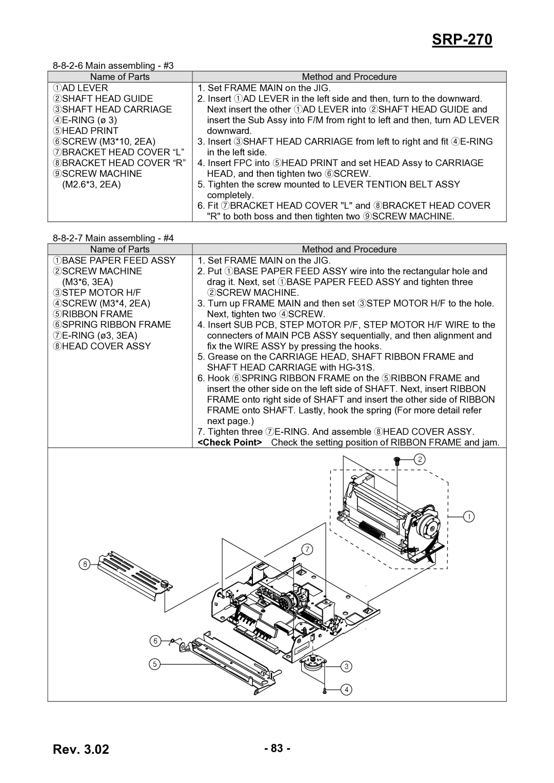
Name of Parts
①BASE PAPER FEED ASSY
②SCREW MACHINE (M3*6, 3EA)
③STEP MOTOR H/F
④SCREW (M3*4, 2EA)
⑤RIBBON FRAME
⑥SPRING RIBBON FRAME
⑧HEAD COVER ASSY
Method and Procedure
1.Set FRAME MAIN on the JIG.
2.Put ①BASE PAPER FEED ASSY wire into the rectangular hole and drag it. Next, set ①BASE PAPER FEED ASSY and tighten three
②SCREW MACHINE.
3.Turn up FRAME MAIN and then set ③STEP MOTOR H/F to the hole. Next, tighten two ④SCREW.
4.Insert SUB PCB, STEP MOTOR P/F, STEP MOTOR H/F WIRE to the connecters of MAIN PCB ASSY sequentially, and then alignment and fix the WIRE ASSY by pressing the hooks.
5.Grease on the CARRIAGE HEAD, SHAFT RIBBON FRAME and SHAFT HEAD CARRIAGE with
6.Hook ⑥SPRING RIBBON FRAME on the ⑤RIBBON FRAME and insert the other side on the left side of SHAFT. Next, insert RIBBON FRAME onto right side of SHAFT and insert the other side of RIBBON FRAME onto SHAFT. Lastly, hook the spring (For more detail refer next page.)
7.Tighten three
Rev. 3.02 | - 83 - |