RackSwitch G8000 Application Guide
Example 2
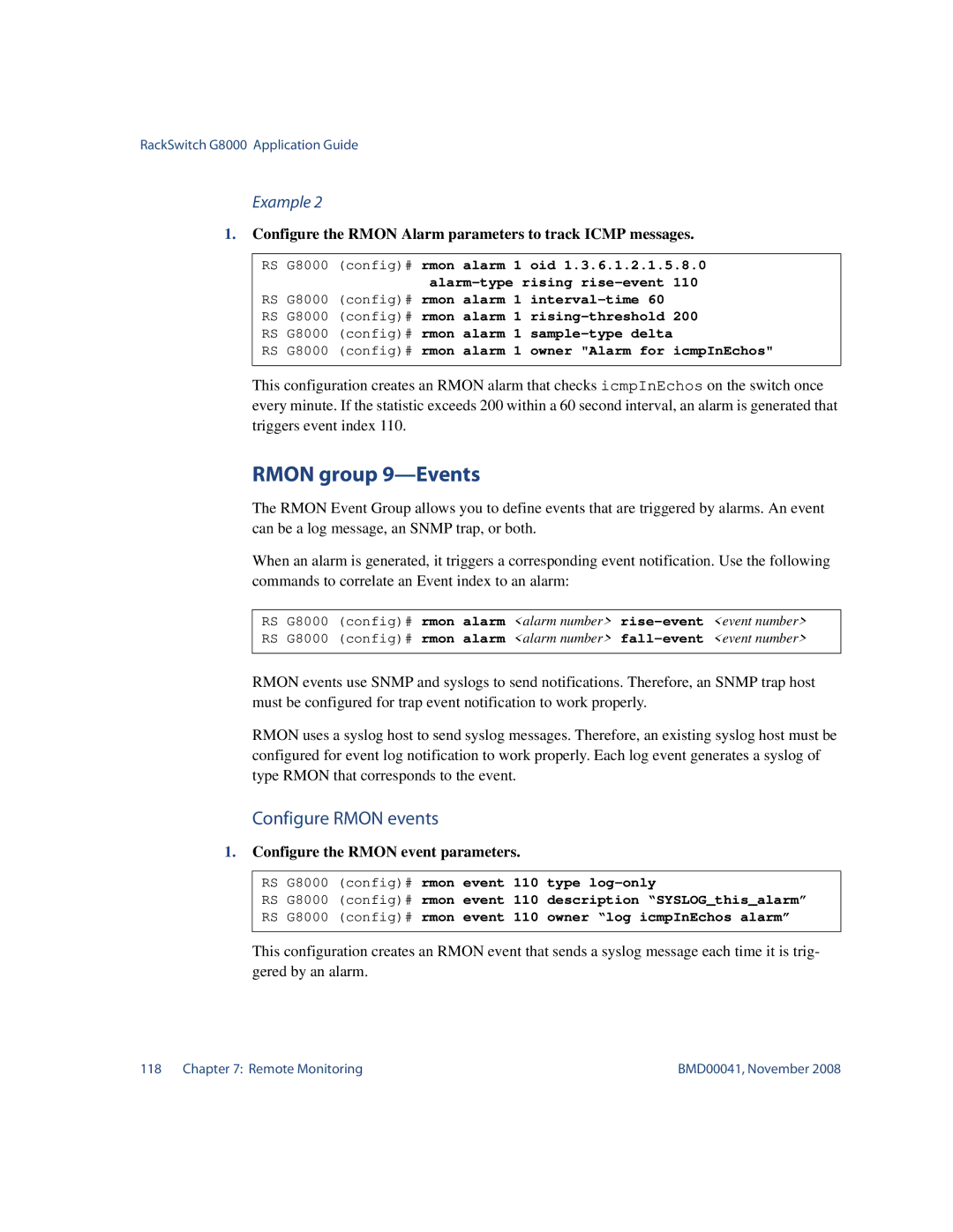
1.Configure the RMON Alarm parameters to track ICMP messages.
RS G8000 (config)# rmon alarm 1 oid 1.3.6.1.2.1.5.8.0
RS G8000 |
| 110 | |||||
(config)# rmon alarm 1 | 200 | ||||||
RS G8000 | (config)# rmon alarm 1 | ||||||
RS | G8000 | (config)# | rmon | alarm | 1 | icmpInEchos" | |
RS | G8000 | (config)# | rmon | alarm | 1 | owner "Alarm for | |
This configuration creates an RMON alarm that checks icmpInEchos on the switch once every minute. If the statistic exceeds 200 within a 60 second interval, an alarm is generated that triggers event index 110.
RMON group 9—Events
The RMON Event Group allows you to define events that are triggered by alarms. An event can be a log message, an SNMP trap, or both.
When an alarm is generated, it triggers a corresponding event notification. Use the following commands to correlate an Event index to an alarm:
RS G8000 (config)# rmon alarm <alarm number>
RMON events use SNMP and syslogs to send notifications. Therefore, an SNMP trap host must be configured for trap event notification to work properly.
RMON uses a syslog host to send syslog messages. Therefore, an existing syslog host must be configured for event log notification to work properly. Each log event generates a syslog of type RMON that corresponds to the event.
Configure RMON events
1.Configure the RMON event parameters.
RS G8000 | (config)# rmon event 110 | type | ||||
RS | G8000 | (config)# | rmon | event | 110 | description “SYSLOG_this_alarm” |
RS | G8000 | (config)# | rmon | event | 110 | owner “log icmpInEchos alarm” |
This configuration creates an RMON event that sends a syslog message each time it is trig- gered by an alarm.
118 Chapter 7: Remote Monitoring | BMD00041, November 2008 |