RackSwitch G8000 Application Guide
Example of Subnet Routing
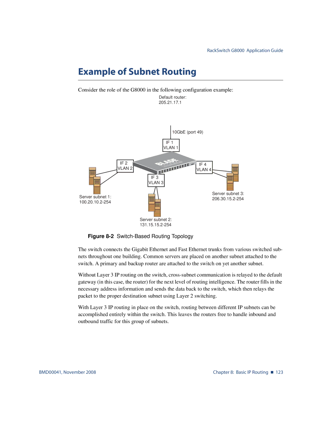
Consider the role of the G8000 in the following configuration example:
Default router: 205.21.17.1
IF 2
VLAN 2
Server subnet 1:
10GbE (port 49)
IF 1
VLAN 1
IF 4
VLAN 4
IF 3
VLAN 3
Server subnet 3:
Server subnet 2:
Figure 8-2 Switch-Based Routing Topology
The switch connects the Gigabit Ethernet and Fast Ethernet trunks from various switched sub- nets throughout one building. Common servers are placed on another subnet attached to the switch. A primary and backup router are attached to the switch on yet another subnet.
Without Layer 3 IP routing on the switch,
With Layer 3 IP routing in place on the switch, routing between different IP subnets can be accomplished entirely within the switch. This leaves the routers free to handle inbound and outbound traffic for this group of subnets.
BMD00041, November 2008 | Chapter 8: Basic IP Routing 123 |