RackSwitch G8000 Application Guide
VLANs and Port VLAN ID Numbers
VLAN numbers
The G8000 supports up to 1024 VLANs per switch. Even though the maximum number of VLANs supported at any given time is 1024, each can be identified with any number between 1 and 4094. VLAN 1 is the default VLAN for all ports.
Viewing VLANs
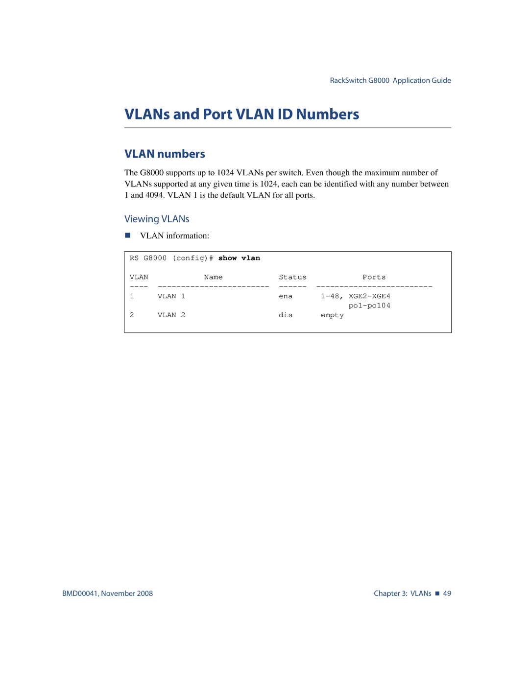
VLAN information:
RS G8000 (config)# show vlan |
|
| |
VLAN | Name | Status | Ports |
1 | VLAN 1 | ena | |
2 | VLAN 2 | dis | |
empty | |||
|
|
|
|
BMD00041, November 2008 | Chapter 3: VLANs 49 |