D9412GV3/D7412GV3
Control Panels
Trademarks
Certifications and Approvals
Listings and Approvals
Federal Communications Commission FCC Rules
Ringer Equivalence: 0.0B
Service Center in USA
FCC Registration Number
Contents
Appendix B: Point Address Charts
13.0 Programmer and Accessory Connections
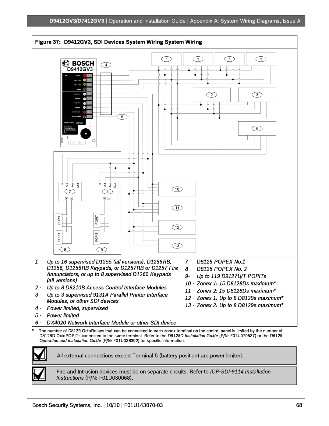
Appendix A: System Wiring Diagrams, Issue A
Tables
Figures
Table 1: Related Documentation
1.0 Introduction
Introduction
2.2Precautions during Installation
2.0 Lightning Strikes
2.1Effects
Lightning Strikes
3.1Configuration and Parts
Figure 1: System Configuration
3.0Overview
Overview
3.1.1Parts List
Assembly
Literature Pack
3.1.2Parts Available by Separate Order
Overview
3.2Accessories
Table 3: Compatible Accessories1
3.3Features in the D9412GV3 and D7412GV3
3.3.1SDI Molex Connector
3.3.2Tip and Ring Posts
3.3.3Telephone Line Sniff
3.3.8Keyswitch
3.3.9Access Control
3.3.12 Ground Fault Detection
3.3.7Keypads
4.0Installation
4.1Installation Preparation
Installation
3.3.13 Ground Fault Detection Added Feature
4.4Installing the Control Panel
4.5Connecting Earth Ground
4.5.2Ground Fault Detect Enable
Figure 2: Enclosure Mounting
4.5.3Enabling Ground Fault Detection
Figure 3: Enabling Ground Fault Detection
4.5.4Ground Fault Specifications
Table 5: Ground Fault Impedance Specifications
4.6Completing the Installation
4.6.1Charging the Battery
4.6.2Installing and Wiring Detection Devices
4.6.3Installing Modules and Relays
4.8Installing the Point Chart Label
4.9Testing the System
4.10Service Walk Test
Service Walk Test Procedure
Installation
b.Press the ESC key. VIEW UNTESTED ? appears
Installation
Figure 5 D9412GV3 Service Walk Test Flow Chart
SERVICE WALK?
246 PTS TO TEST
Figure 6: D7412GV3 Service Walk Test Flow Chart
75 PTS TO TEST
74 PTS TO TEST
73 PTS TO TEST
5.0Power Supply
5.1Primary Power Terminals 1 and
5.2Secondary Power Terminals
Power Supply
Power Supply
Figure 7: Battery Terminals
Figure 8: Non-Power-LimitedWiring
Replacing the Battery
Charging and Battery LEDs
D8132 Boost Battery Backup: Adding a D8132
Investigate Low Battery reports immediately: If
5.2.6Battery Discharge and Recharge Schedule
Table 6: Battery Discharge and Recharge Schedule
Charging Status and Low Battery LEDs
Power Supply
6.0Power Outputs
6.2Total Available Power
Power Outputs
6.1Circuit Protection
6.4Programmable Power Output Terminals 6, 7, and
6.4.3Fire System Power Formula
Verification and Reset Relay
6.4.1Programming
Figure 10: RJ31X Wiring
7.0Telephone Connections
7.1Registration
7.2Notification
7.5Phone LED Red
7.6Operation Monitor LED Green
7.7Dialing Format
7.8Telephone Line Monitor
7.11D928 Dual Phone Line Switcher
Figure 12: D928 Dual Phone Line Switcher
7.11.1 Description
7.11.2 Operation
7.11.3Installing the D928 Mounting
Wiring
AC Power LED
8.0On-BoardPoints
Figure 13: On-boardPoint Sensor Loop Wiring
8.3Point Parameters
Point Parameters
On-BoardPoints
8.4Point Response Time
On-BoardPoints
On-BoardPoints
On-BoardPoints
9.0Off-BoardPoints
9.1Point Zonex Bus D9412GV3
Terminals and D7412GV3 Terminals
Off-BoardPoints
Table 12 Off-BoardPoint Errors
9.2D8125 and D9127 POPIT Modules
Listings
Off-BoardPoints
For system supervision, do not use looped wire terminals. Break the wire run to provide supervision of the connections
Off-BoardPoints
For system supervision, do not use looped wire terminals. Break the wire run to provide supervision of the connections
Off-BoardPoints
9.3 Installing the D8125 POPEX Module
9.3.2Wiring the D8125 to the Control Panel
9.3.3Wiring POPITs to the Data Expansion Loop
Table 13: Data Expansion Loop Wire Specifications
9.3.4Wiring Data Expansion Loops to POPEX Modules
9.3.5POPIT Sensor Loops
9.3.6POPIT Module Point Assignments
9.3.7Program Record Sheet
9.4D8128D OctoPOPIT Module
Figure 18: Program Record Sheet
9.3.8POPIT Labels
9.4.1Description
9.4.2Listings
Requirements for Fire Initiation Applications
Figure 19 D8128D OctoPOPIT Layout
Off-BoardPoints
9.4.3Installation
9.4.4Setting the OctoPOPIT Switches
Address Switches
Table 15: Switch 5 Settings for Line Termination
9.4.6Wiring OctoPOPITs
Using the Terminal Strip
9.4.5Mounting OctoPOPITs
Table 16: Terminal Strip Connections
For system supervision, do not use looped wire terminals. Break the wire run to provide supervision of the connections
Off-BoardPoints
For system supervision, do not use looped wire terminals. Break the wire run to provide supervision of the connections
Off-BoardPoints
Using Molex Connectors
Off-BoardPoints
9.5Testing Off-BoardPoints
9.4.7OctoPOPIT Sensor Loops
Figure 23: D8128D OctoPOPIT Sensor Loops
Off-BoardPoints
Figure 24: D8129 Connections to the D9412GV3
10.0Off-BoardRelays
10.1D8129 OctoRelay
10.1.1 Configuring the D8129 OctoRelay
Table 17: D8129 OctoRelay Switch Settings
10.1.3 Installation
Figure 25 D8129 Connections to the D7412GV3
10.1.4 Wiring Connections
10.2.2 Installation
10.2D811 Arm Status Relay Module
Table 18: Number of D8128Ds Used with D8129s
10.2.3 Wiring Connections
Figure 26: D811 Module Wiring to the D9412GV3
Figure 27: D811 Module Wiring to the D7412GV3
Table 19: Keypad Address Settings
11.0Arming Devices
11.1Description
11.2Keypad Terminals 29 to
11.2.2 Installation
Wire Limits for Individual Devices
Extra Power for More Keypads
Table 20: Keypad Connections
11.4Keyswitch
Figure 28: Power at Keypads
11.4.3 Installation
11.3D279A Independent Zone Control
Silencing the Bell
Figure 29: Keyswitch Wiring
Momentary Contact
12.2Installation
12.3.1 Switch Settings
Table 22: Printer Address Switch Settings
12.0SDI Devices
12.4.1 Access
12.4.2 Switch Settings
Connecting the D9133DC
12.4D9210B Wiegand Control Interface Module
12.5.3 Address Settings
Figure 30: DX4020 DIP Switch Settings
12.5.2 Network Interface Modules
12.5.4 Supervision
13.0Programmer and Accessory Connections
13.1Programmer Connector
13.2Installer Keypad and Local Programmers Mode
13.3Programmer Access Reports
13.4Accessory Connector
Figure 32: Programmer and Accessory Connections
Figure 33: D9412GV3 Faceplate
14.0Faceplates
14.1D9412GV3 Faceplate
14.2D7412GV3 Faceplate
Figure 34: D7412GV3 Faceplate
Appendix A: System Wiring Diagrams, Issue A
A.1 D9412GV3 Control Panel
D9412GV3
Use zero retard except for waterflow devices
All external connections except Terminal 5 battery position are power limited
A.2 D7412GV3 Control Panel
D7412GV3
Figure 40: D7412GV3, SDI Devices System Wiring
Appendix B: Point Address Charts
Zonex 1 Point Address Chart
B.1 Zonex 1, Points 9 to 127 D9412GV3
Zonex 1, Points 9 to 75 D7412GV3
Zonex 2 Point Address Chart
Zonex 2, Points 129 to 247 D9412GV3 Only
Specifications
Table 26: Specifications
Page
Bosch Security Systems, Inc.,
Bosch Security Systems, Inc
130 Perinton Parkway Fairport, NY USA