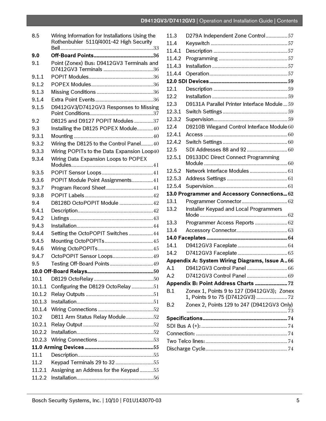
D9412GV3, D7412GV3 specifications
The Bosch Appliances D9412GV3 is a perfect blend of functionality and innovation, designed to meet the needs of modern households. This dishwasher is part of Bosch's reputation for creating high-quality, energy-efficient home appliances. With a sleek design and advanced technology, the D9412GV3 stands out in the crowded market of dishwashers.One of the main features of the D9412GV3 is its remarkable efficiency. With an Energy Star rating, this model is designed to minimize water and energy consumption while still delivering exceptional cleaning performance. The EcoSense technology optimizes water usage, ensuring every wash cycle is both effective and economical, making it a responsible choice for energy-conscious consumers.
The dishwasher offers a spacious interior, capable of accommodating large loads. Its flexible rack system includes adjustable tines and folding platforms, making it easy to fit various dish sizes, from pots and pans to delicate glassware. Additionally, the third rack feature provides extra space for utensils and smaller items, enhancing its capacity and versatility.
In terms of cleaning power, the D9412GV3 is equipped with the PrecisionWash system. This cutting-edge technology features intelligent sensors that continuously scan and check the load, adjusting the wash cycle as needed for optimal results. Coupled with the 40 dBA noise level, it ensures that the dishwasher operates quietly in the background, so you can enjoy your home without disruptive sounds.
Another standout characteristic is the PureDry technology, an integrated drying system that uses a condensation process to gently dry dishes without the need for extra heat. This not only protects sensitive items but also saves energy, further enhancing the appliance's eco-friendly nature.
Ease of use is a priority for Bosch, as seen in the D9412GV3's user-friendly controls. The intuitive interface allows for selecting various wash cycles and options, including Heavy, Auto, and Quick options, catering to different cleaning needs. Additionally, the Time Delay feature provides the flexibility to set the dishwasher to run at a later time, great for aligning with your schedule.
In summary, the Bosch D9412GV3 combines innovative technologies with a user-centered design to deliver a top-tier dishwasher experience. Its energy-efficient operation, spacious interior, and advanced cleaning features make it an excellent choice for any kitchen, ensuring spotless dishes with minimal effort. With Bosch's commitment to quality, the D9412GV3 stands as a reliable and stylish addition to any modern home.

