TTW1 Universal Service
Replacement Blower
MITW -12 / -15 Series
Step 9.
f.) Verify that all electrical connections have been modified, as previously indicated. Also, verify that the pressure switch tubing is connected to the pressure tap on the blower
and to the switch itself. Ensure that the tubing is not kinked.
Step 10.
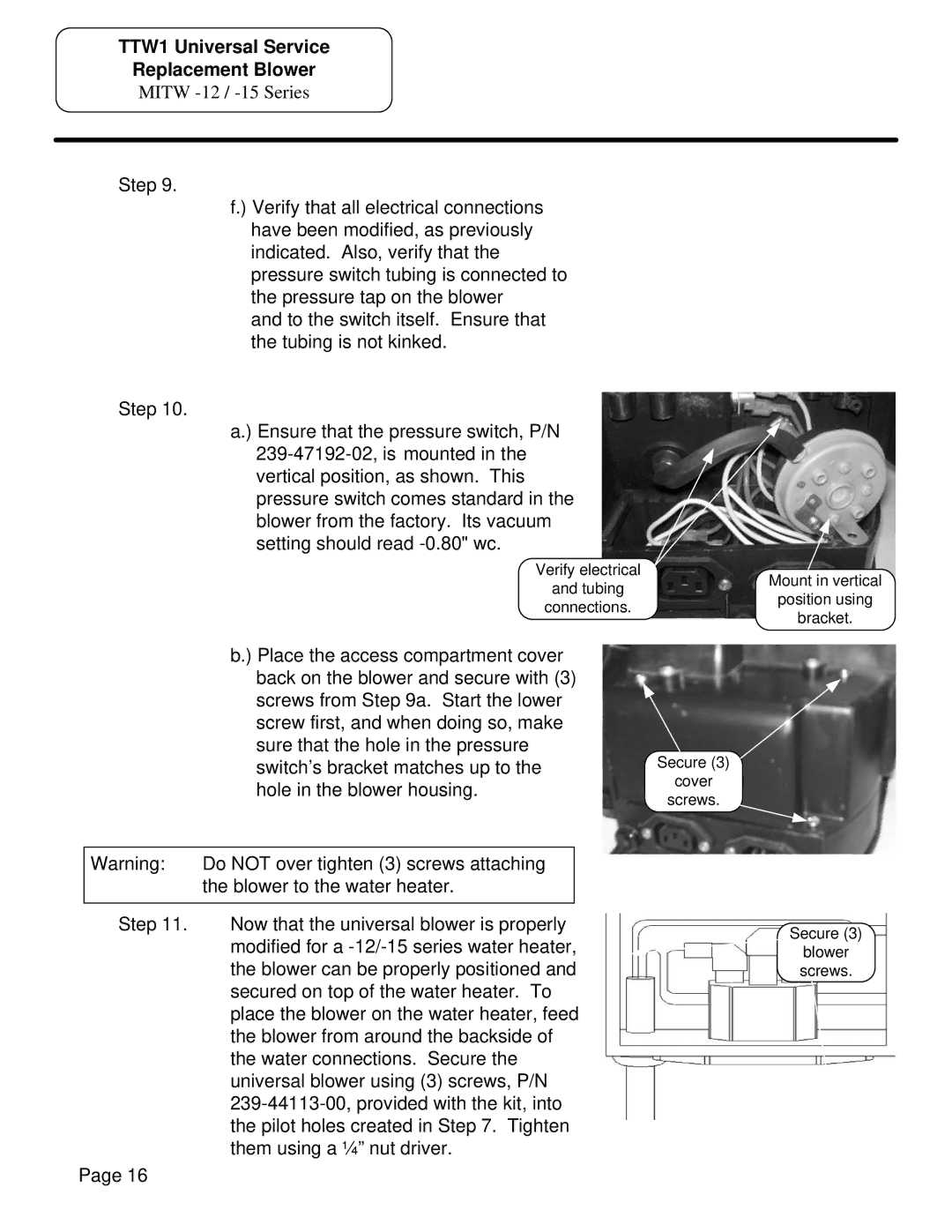
a.) Ensure that the pressure switch, P/N
Verify electrical
and tubing
connections.
Mount in vertical
position using
bracket.
b.) Place the access compartment cover
|
| back on the blower and secure with (3) | |
|
| screws from Step 9a. Start the lower | |
|
| screw first, and when doing so, make | |
|
| sure that the hole in the pressure | |
|
| switch’s bracket matches up to the | |
|
| hole in the blower housing. | |
|
|
| |
| Warning: | Do NOT over tighten (3) screws attaching |
|
|
| the blower to the water heater. |
|
|
|
|
|
| Step 11. | Now that the universal blower is properly | |
|
| modified for a | |
|
| the blower can be properly positioned and | |
|
| secured on top of the water heater. To | |
|
| place the blower on the water heater, feed | |
|
| the blower from around the backside of | |
|
| the water connections. Secure the | |
|
| universal blower using (3) screws, P/N | |
|
| ||
|
| the pilot holes created in Step 7. Tighten | |
|
| them using a ¼” nut driver. | |
Page 16 |
|
| |
Secure (3)
cover
screws.
Secure (3)