Specifications
| Control Timings |
|
|
Ignition State | Timing |
|
|
15 seconds | |
|
|
Trial for Ignition | 90 seconds |
|
|
Flame Stabilization Period | 3 seconds |
|
|
15 seconds | |
|
|
Flame Failure Response Time | 1.5 seconds (2 second maximum, 1 second minimum) |
|
|
15 seconds | |
|
|
PS Fault Delay (failed open/close) | Retry after 2 minutes |
|
|
Soft Lockout | Retry after 5 minutes |
|
|
TCO Limit Lockout | Indefinite (see page 34 to reset) |
|
|
Verify Resistive Delay | Retry after 2 minutes (repeats 5 times) |
|
|
Simulated Resistive Load Lockout | Indefinite (cycle power to reset) |
|
|
Hardware Error Lockout | Indefinite (self clears if fault clears for at least 15 seconds) |
|
|
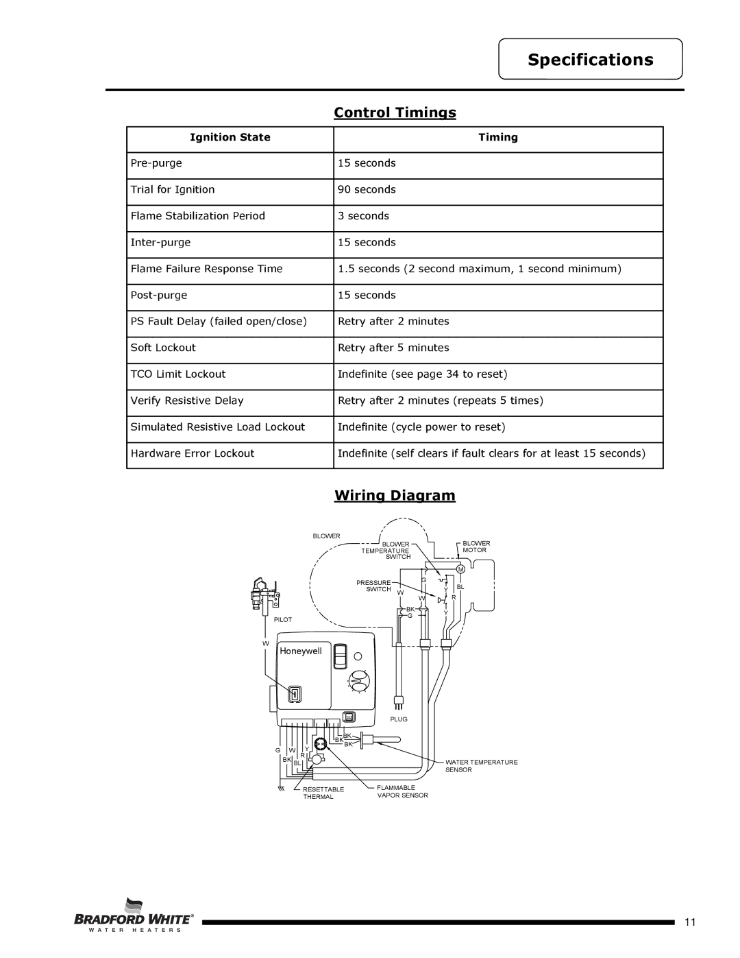
Wiring Diagram
BLOWER |
|
|
|
BLOWER |
|
| BLOWER |
TEMPERATURE |
|
| MOTOR |
SWITCH |
|
|
|
|
|
| M |
PRESSURE | G |
|
|
|
| BL | |
SWITCH W |
| Y | |
|
| ||
| W |
| R |
BK |
| Y |
|
G |
|
| |
|
|
| |
PILOT |
|
|
|
W
Honeywell
| PLUG |
| BKBK |
| BK |
G W | Y |
| |
R |
|
BK BL | WATER TEMPERATURE |
| SENSOR |
RESETTABLE | FLAMMABLE |
| |
THERMAL | VAPOR SENSOR |
|
Page 11
11