580F specifications
The Bryant 580F is a highly regarded gas furnace known for its exceptional heating performance and advanced technology. Designed for residential use, this model stands out for its reliability, efficiency, and user-friendly features that cater to modern heating demands.One of the most notable features of the Bryant 580F is its efficiency rating. With an AFUE (Annual Fuel Utilization Efficiency) rating of up to 95%, this furnace maximizes heat output while minimizing energy consumption. This high level of efficiency not only results in lower utility bills but also reduces the environmental impact—a critical consideration for today’s eco-conscious homeowners.
The Bryant 580F is equipped with a multi-speed blower that ensures consistent airflow and enhances comfort by maintaining even temperatures throughout the home. This technology allows the furnace to adjust its operation based on the heating needs, leading to quieter operation and increased comfort levels.
In terms of construction, the Bryant 580F is built with durable materials that promise longevity and resilience against wear and tear. Its compact design makes installation easier, allowing it to fit into tight spaces without compromising its performance.
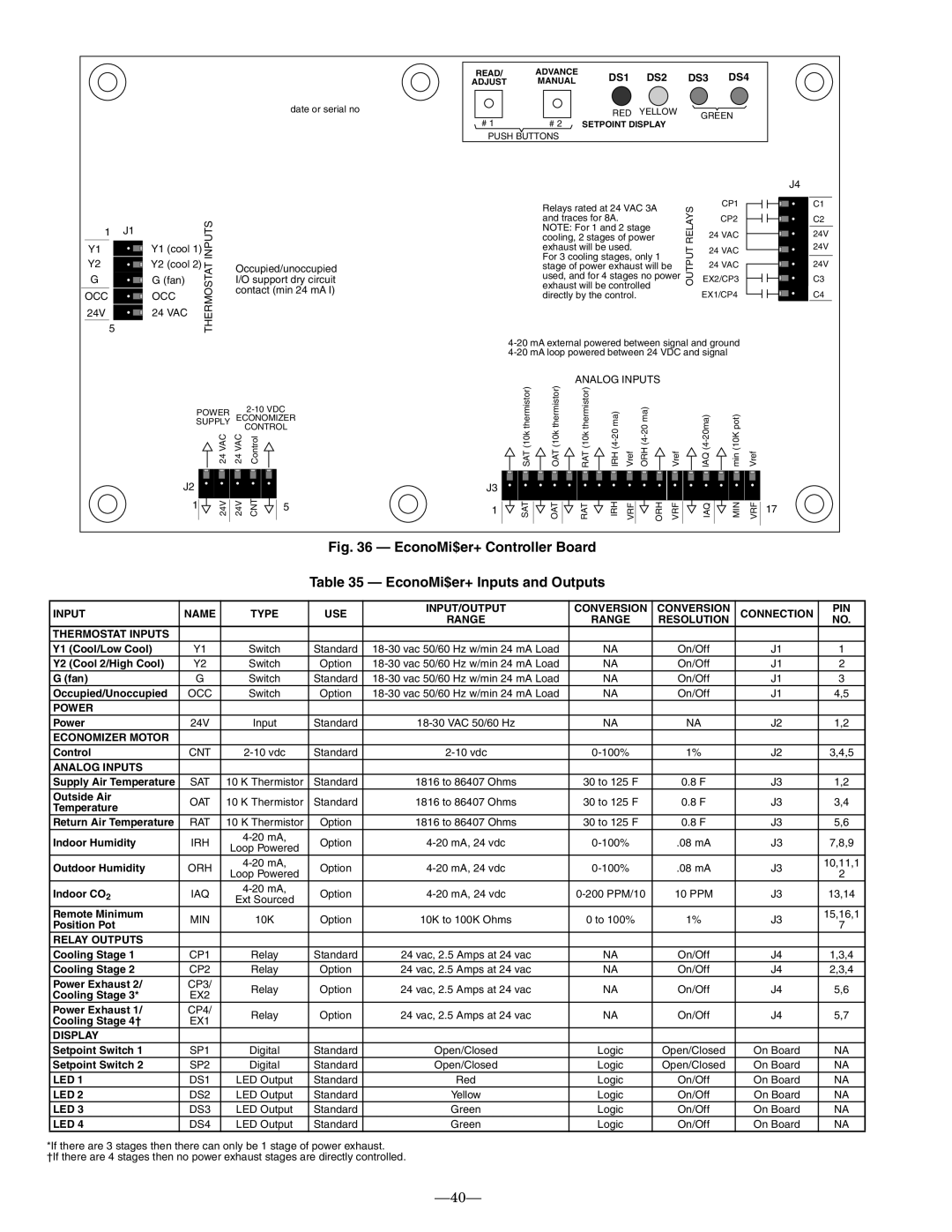
One of the standout technologies integrated into the Bryant 580F is its enhanced control system. The furnace works seamlessly with smart thermostats, allowing homeowners to monitor and adjust heating settings from their mobile devices. This feature not only provides convenience but also allows for energy-saving optimizations based on personal schedules and preferences.
Safety is also a primary concern with the Bryant 580F. It includes robust safety features such as a hot surface ignition system that eliminates the need for a standing pilot light, reducing the risk of gas leaks. Additionally, advanced diagnostics help in troubleshooting and maintenance, ensuring that potential issues can be identified and resolved quickly.
In conclusion, the Bryant 580F gas furnace is a remarkable choice for those seeking a blend of efficiency, comfort, and advanced technology. Its high AFUE rating, multi-speed blower, smart control compatibility, and safety features make it a reliable option for homeowners looking to invest in a dependable heating solution. As the demand for energy-efficient heating continues to grow, the Bryant 580F stands out as a model that meets and exceeds expectations in the modern heating landscape.

