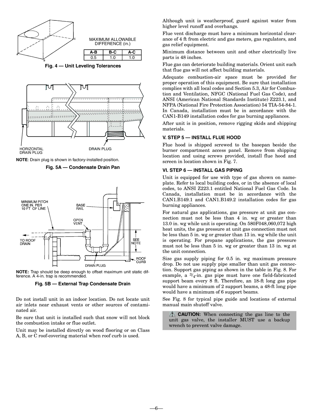
MAXIMUM ALLOWABLE

DIFFERENCE (in.)

A-B

B-C

A-C

0.5

1.0

1.0

Fig. 4 — Unit Leveling Tolerances

HORIZONTAL

DRAIN PLUG

DRAIN PLUG


NOTE: Drain plug is shown in factory-installed position.

Fig. 5A — Condensate Drain Pan

NOTE: Trap should be deep enough to offset maximum unit static dif- ference. A 4-in. trap is recommended.

Fig. 5B — External Trap Condensate Drain

Do not install unit in an indoor location. Do not locate unit air inlets near exhaust vents or other sources of contami- nated air.

Be sure that unit is installed such that snow will not block the combustion intake or flue outlet.

Unit may be installed directly on wood flooring or on Class A, B, or C roof-covering material when roof curb is used.

Although unit is weatherproof, guard against water from higher level runoff and overhangs.

Flue vent discharge must have a minimum horizontal clear- ance of 4 ft from electric and gas meters, gas regulators, and gas relief equipment.

Minimum distance between unit and other electrically live parts is 48 inches.

Flue gas can deteriorate building materials. Orient unit such that flue gas will not affect building materials.

Adequate combustion-air space must be provided for proper operation of this equipment. Be sure that installation complies with all local codes and Section 5.3, Air for Combus- tion and Ventilation, NFGC (National Fuel Gas Code), and ANSI (American National Standards Institute) Z223.1, and NFPA (National Fire Protection Association) 54 TIA-54-84-1. In Canada, installation must be in accordance with the CAN1-B149 installation codes for gas burning appliances.

After unit is in position, remove rigging skids and shipping materials.

V. STEP 5 — INSTALL FLUE HOOD

Flue hood is shipped screwed to the basepan beside the burner compartment access panel. Remove from shipping location and using screws provided, install flue hood and screen in location shown in Fig. 7.

VI. STEP 6 — INSTALL GAS PIPING

Unit is equipped for use with type of gas shown on name- plate. Refer to local building codes, or in the absence of local codes, to ANSI Z223.1 entitled National Fuel Gas Code. In Canada, installation must be in accordance with the CAN1.B149.1 and CAN1.B149.2 installation codes for gas burning appliances.

For natural gas applications, gas pressure at unit gas con- nection must not be less than 4 in. wg or greater than

13.0in. wg while unit is operating. On 580F048,060,072 high heat units, the gas pressure at unit gas connection must not be less than 5 in. wg or greater than 13 in. wg while the unit is operating. For propane applications, the gas pressure must not be less than 5 in. wg or greater than 13 in. wg at the unit connection.

Size gas supply piping for 0.5 in. wg maximum pressure drop. Do not use supply pipe smaller than unit gas connec- tion. Support gas piping as shown in the table in Fig. 8. For example, a 3/4-in. gas pipe must have one field-fabricated support beam every 8 ft. Therefore, an 18-ft long gas pipe would have a minimum of 2 support beams, a 48-ft long pipe would have a minimum of 6 support beams.

See Fig. 8 for typical pipe guide and locations of external manual main shutoff valve.

CAUTION: When connecting the gas line to the unit gas valve, the installer MUST use a backup wrench to prevent valve damage.

6

Page 6
Image 6
Bryant 580F installation instructions Install Flue Hood, VI. Install GAS Piping

580F specifications

The Bryant 580F is a highly regarded gas furnace known for its exceptional heating performance and advanced technology. Designed for residential use, this model stands out for its reliability, efficiency, and user-friendly features that cater to modern heating demands.

One of the most notable features of the Bryant 580F is its efficiency rating. With an AFUE (Annual Fuel Utilization Efficiency) rating of up to 95%, this furnace maximizes heat output while minimizing energy consumption. This high level of efficiency not only results in lower utility bills but also reduces the environmental impact—a critical consideration for today’s eco-conscious homeowners.

The Bryant 580F is equipped with a multi-speed blower that ensures consistent airflow and enhances comfort by maintaining even temperatures throughout the home. This technology allows the furnace to adjust its operation based on the heating needs, leading to quieter operation and increased comfort levels.

In terms of construction, the Bryant 580F is built with durable materials that promise longevity and resilience against wear and tear. Its compact design makes installation easier, allowing it to fit into tight spaces without compromising its performance.

One of the standout technologies integrated into the Bryant 580F is its enhanced control system. The furnace works seamlessly with smart thermostats, allowing homeowners to monitor and adjust heating settings from their mobile devices. This feature not only provides convenience but also allows for energy-saving optimizations based on personal schedules and preferences.

Safety is also a primary concern with the Bryant 580F. It includes robust safety features such as a hot surface ignition system that eliminates the need for a standing pilot light, reducing the risk of gas leaks. Additionally, advanced diagnostics help in troubleshooting and maintenance, ensuring that potential issues can be identified and resolved quickly.

In conclusion, the Bryant 580F gas furnace is a remarkable choice for those seeking a blend of efficiency, comfort, and advanced technology. Its high AFUE rating, multi-speed blower, smart control compatibility, and safety features make it a reliable option for homeowners looking to invest in a dependable heating solution. As the demand for energy-efficient heating continues to grow, the Bryant 580F stands out as a model that meets and exceeds expectations in the modern heating landscape.