Hardware Specifications
C.2.5.1 Connecting Switches with TP25 Network Modules
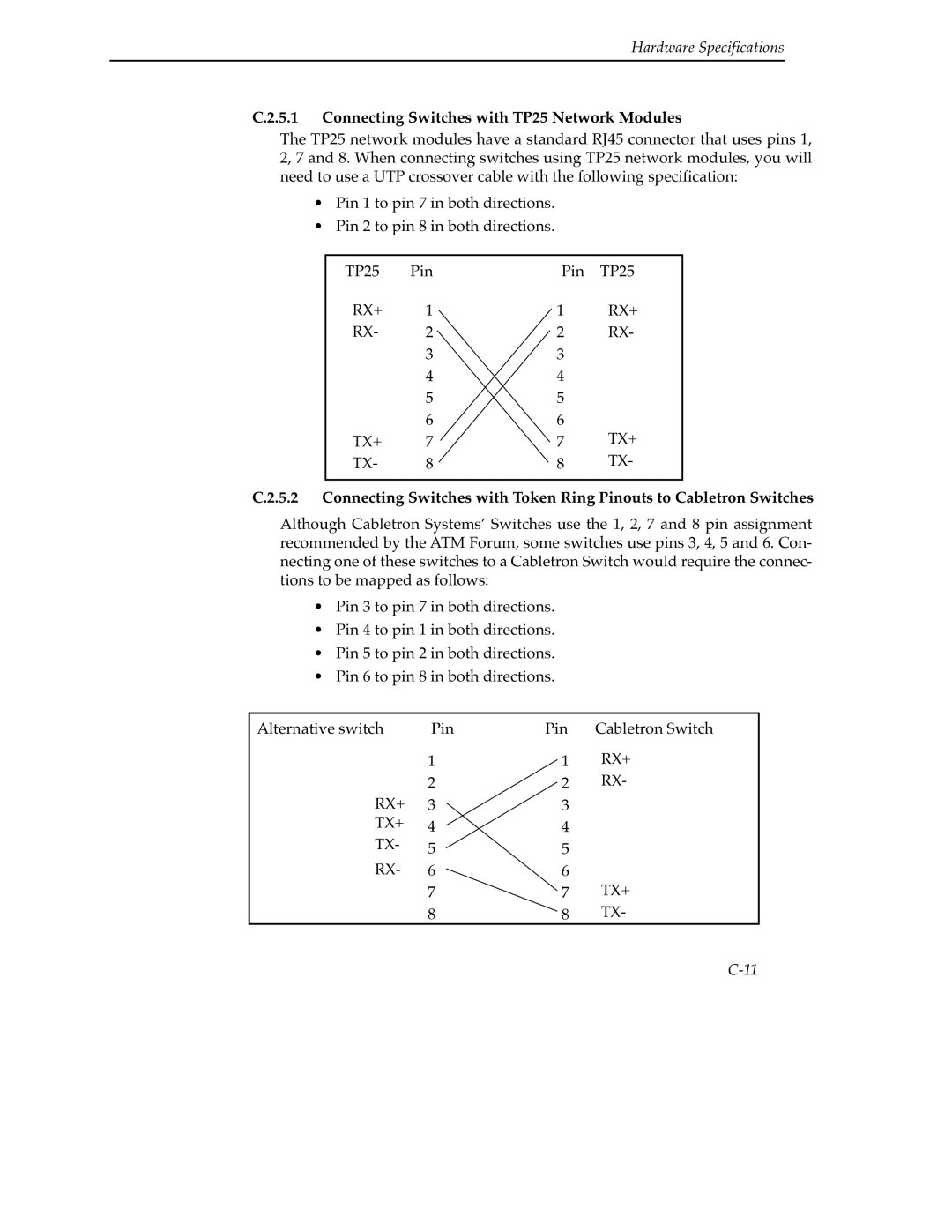
The TP25 network modules have a standard RJ45 connector that uses pins 1, 2, 7 and 8. When connecting switches using TP25 network modules, you will need to use a UTP crossover cable with the following specification:
•Pin 1 to pin 7 in both directions.
•Pin 2 to pin 8 in both directions.
TP25 | Pin | Pin | TP25 |
RX+ | 1 | 1 | RX+ |
RX- | 2 | 2 | RX- |
| 3 | 3 |
|
| 4 | 4 |
|
| 5 | 5 |
|
| 6 | 6 |
|
TX+ | 7 | 7 | TX+ |
TX- | 8 | 8 | TX- |
|
|
|
|
C.2.5.2 Connecting Switches with Token Ring Pinouts to Cabletron Switches
Although Cabletron Systems’ Switches use the 1, 2, 7 and 8 pin assignment recommended by the ATM Forum, some switches use pins 3, 4, 5 and 6. Con- necting one of these switches to a Cabletron Switch would require the connec- tions to be mapped as follows:
•Pin 3 to pin 7 in both directions.
•Pin 4 to pin 1 in both directions.
•Pin 5 to pin 2 in both directions.
•Pin 6 to pin 8 in both directions.
Alternative switch | Pin | Pin | Cabletron Switch |
| 1 | 1 | RX+ |
| 2 | 2 | RX- |
RX+ | 3 | 3 |
|
TX+ | 4 | 4 |
|
TX- | 5 | 5 |
|
RX- | 6 | 6 |
|
| 7 | 7 | TX+ |
| 8 | 8 | TX- |