Introduction
|
|
|
|
|
| SecureFast Cell | |||
| RX1 | RX2 | RX3 | RX4 |
| RX1 | RX2 | RX3 | RX4 |
| TX1 | TX2 | TX3 | TX4 |
| TX1 | TX2 | TX3 | TX4 |
| RX1 | RX2 | RX3 | RX4 |
| RX1 | RX2 | RX3 | RX4 |
| TX1 | TX2 | TX3 | TX4 |
| TX1 | TX2 | TX3 | TX4 |
| Tx | Rx |
| PWR |
| Tx | Rx |
| PWR |
| C | L |
|
|
| ||||
RESET |
|
|
| SFCS | RESET | C | L |
| FORE - FORE |
|
|
|
|
|
|
|
| ||
SER | ETH | NEXT | SELECT | SER | ETH | NEXT SELECT |
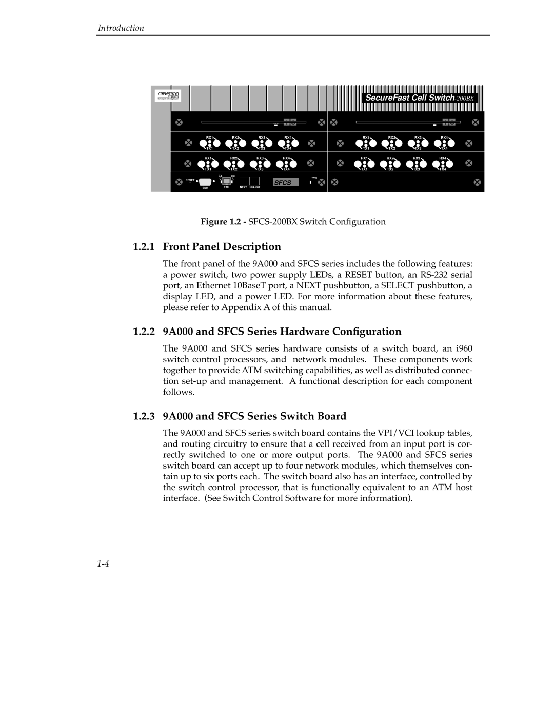
Figure 1.2 - SFCS-200BX Switch Configuration
1.2.1 Front Panel Description
The front panel of the 9A000 and SFCS series includes the following features: a power switch, two power supply LEDs, a RESET button, an
1.2.2 9A000 and SFCS Series Hardware Configuration
The 9A000 and SFCS series hardware consists of a switch board, an i960 switch control processors, and network modules. These components work together to provide ATM switching capabilities, as well as distributed connec- tion
1.2.3 9A000 and SFCS Series Switch Board
The 9A000 and SFCS series switch board contains the VPI/VCI lookup tables, and routing circuitry to ensure that a cell received from an input port is cor- rectly switched to one or more output ports. The 9A000 and SFCS series switch board can accept up to four network modules, which themselves con- tain up to six ports each. The switch board also has an interface, controlled by the switch control processor, that is functionally equivalent to an ATM host interface. (See Switch Control Software for more information).