Switch Hardware
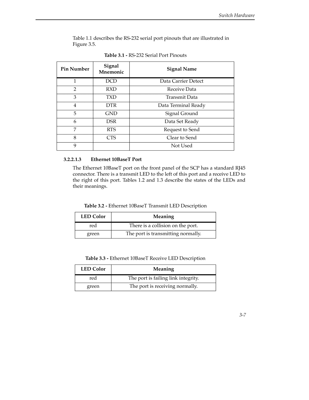
Table 1.1 describes the
Table 3.1 - RS-232 Serial Port Pinouts
Pin Number | Signal | Signal Name | |
Mnemonic | |||
|
| ||
|
|
| |
1 | DCD | Data Carrier Detect | |
|
|
| |
2 | RXD | Receive Data | |
|
|
| |
3 | TXD | Transmit Data | |
|
|
| |
4 | DTR | Data Terminal Ready | |
|
|
| |
5 | GND | Signal Ground | |
|
|
| |
6 | DSR | Data Set Ready | |
|
|
| |
7 | RTS | Request to Send | |
|
|
| |
8 | CTS | Clear to Send | |
|
|
| |
9 |
| Not Used | |
|
|
|
3.2.2.1.3Ethernet 10BaseT Port
The Ethernet 10BaseT port on the front panel of the SCP has a standard RJ45 connector. There is a transmit LED to the left of this port and a receive LED to the right of this port. Tables 1.2 and 1.3 describe the states of the LEDs and their meanings.
Table 3.2 - Ethernet 10BaseT Transmit LED Description
LED Color | Meaning |
|
|
red | There is a collision on the port. |
|
|
green | The port is transmitting normally. |
|
|
Table 3.3 - Ethernet 10BaseT Receive LED Description
LED Color | Meaning |
|
|
red | The port is failing link integrity. |
|
|
green | The port is receiving normally. |
|
|
