Contents
Safety Considerations
Contents
General
Introduction
Unit Nominal Section a Section B 30GTN,R Tons Unit 30GTN,R
Major System Components
Unit Sizes and Modular Combinations 30GTN,R
Unit Sizes and Modular Combinations 30GUN,R
Control Module Communication
Carrier Comfort Network CCN Interface
Thermistor Designations
Output Relay
Status Switches
Page
24 V Control Schematic, Unit Sizes
24 V Control Schematic, Unit Sizes 080-110, 230B-315B
CCN LEN Data Communication Port
Main Base Board
040-110 130-210
Operating Data
Thermistor T3 and T4 Locations
Compressor Thermistor Locations T7 and T8
Columbia D6451 Manhattan M13402 M64430 Quabik 6130
Regular Wiring Plenum Wiring Alpha 1895 American
Manufacturer
Belden 8205
Compressor Protection Control System Module Sizes
Stepper Motor 12 VDC
CEPL130351
Approx
Part Load Data Percent Displacement, Standard Units
Displacement Compressors
30GUN,R
255A 60 Hz
110, 290B
390B 50 Hz
330A/B
360B 50 Hz
390B 60 Hz
B1†
A1,B1 A1†,A2,B1 A1*,B1†,B2
Unloaded compressor Two unloaders, both unloaded
190, 290A, 360A/B
170, 270A
A1*,B1*,B2
150-210
Required Hardware for Additional Unloaders
Pumpout
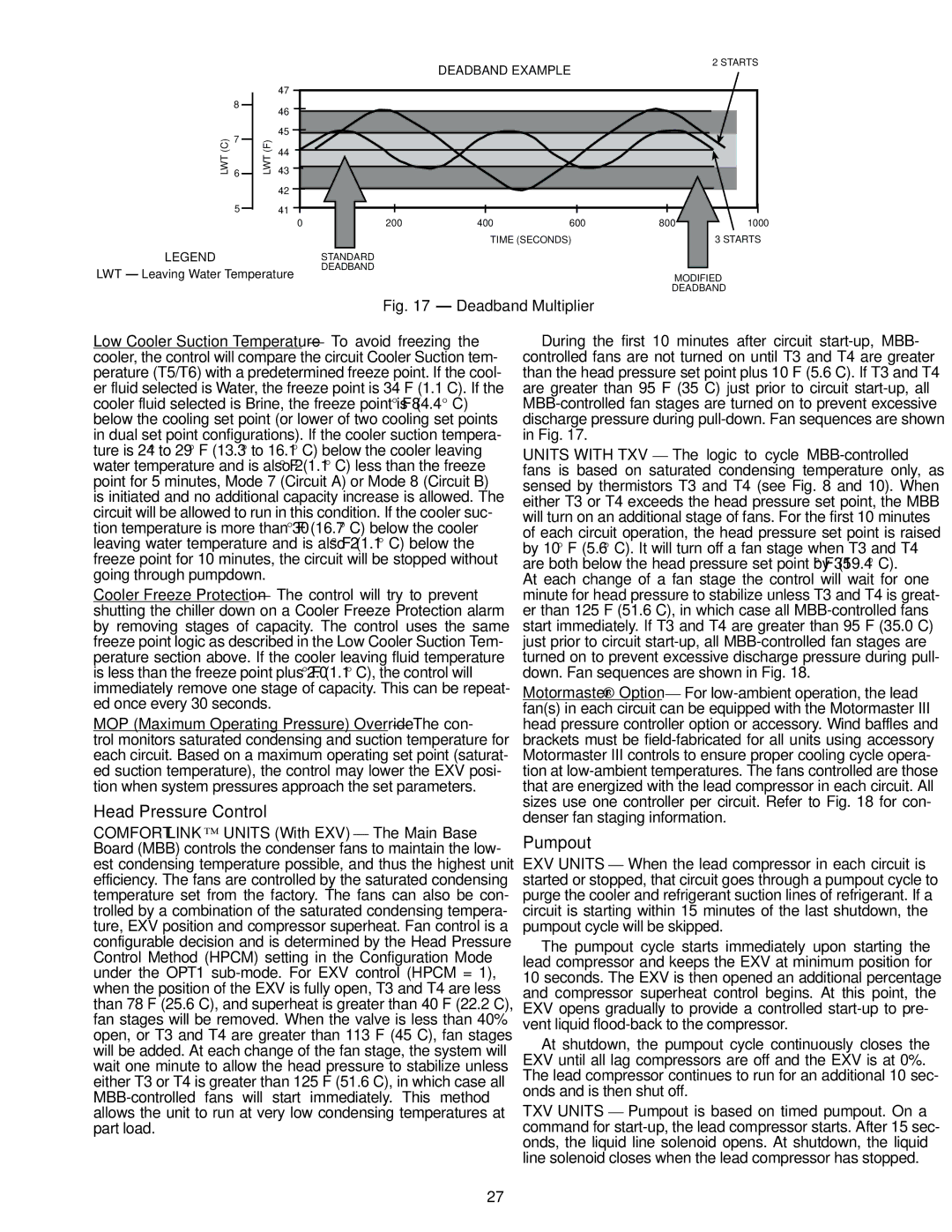
Head Pressure Control
FAN Arrangement FAN Relay Normal Control
Power
Scrolling Marquee Display
Service Test See Both main power
GEN.O Test
Modes
Vers
Run Status Mode and Sub-Mode Directory
SUB-MODE Keypad Range Item Expansion Comment Entry View
Strt
Service Test Mode and Sub-Mode Directory
SUB-MODE Keypad Range Item Expansion Comment Entry Test
Outs
Temperature Mode and Sub-Mode Directory
Pressure Mode and Sub-Mode Directory
Set Point Mode and Sub-Mode Directory
Crct
Inputs Mode and Sub-Mode Directory
Reading and Changing Chilled Fluid Set Point
SUB-MODE Keypad Range Item Expansion Comment Entry GEN.I
Outputs Mode and Sub-Mode Directory
Configuration Mode and Sub-Mode Directory
SUB-MODE Keypad Range Item Expansion Comment Entry GEN.O
EMM
OPT1
OPT2
CCN
Rset
240
SUB-MODE Keypad Display Item Expansion Comment Entry Rset
Example of Temperature Reset Return Fluid Configuration
Example of Configuring Dual Chiller Control Master Chiller
Example of Configuring Dual Chiller Control Slave Chiller
SUB-MODE Keypad Entry Display Item Expansion Comment Rset
SUB-MODE Keypad Entry Item Expansion Comment Range Time
Example of Compressor Lead/Lag Configuration
Time Clock Mode and Sub-Mode Directory
SUB-MODE Keypad Display Item Expansion Comment Entry OPT2
Operating Mode and Sub-Mode Directory
Setting an Occupied Time Schedule
Operating Modes
Mode no Item Expansion Description
Example of Reading and Clearing Alarms
Alarms Mode and Sub-Mode Directory
Entry Expansion
Configuring Temperature Reset
Mode Keypad SUB-MODE
Configuration
RED LED Entry Expansion Configuration
DLS2
Configuring Demand Limit
To 20 mA Demand Limiting
Troubleshooting
Page
T051
Alarm and Alert Codes
LCW
By Control Method Cause Code Alert GENERATED?
EWT
FSM
T173
T153
T155
T170
T206
T203
T204
T205
Compressor OIL Required
Service
Electronic Components
Oil Charge
Cooler Thermistor Locations
Components for Part Number Plugging
Plugs
Cooler Head Bolt Tightening Sequence Typical Tube Sheet
Condenser Coils
Dimension FAN Type
Condenser Fan Adjustment Hz Low Noise Fan Option Units
Refrigerant Feed Components Each circuit has
Printed Circuit Board Connector
Thermistors Temperature Sensors
5K Thermistor Temperature F vs Resistance/Voltage
Drop B
Drop a
5K Thermistor Temperature C vs Resistance/Voltage
Temp Voltage Resistance Drop
200,510
30GUN,R Units
Pressure Switch Settings Psig kPa
Switch Cutout CUT-IN
30GTN,R Units
System Check
PRE-START-UP
START-UP and Operation
Temperature Limits for Standard Units
Temperature
Maximum Ambient Temperature 125
Field Wiring
Refrigerant Circuit
Nominal and Minimum Cooler Fluid Flow Rates
ALM
CWP
Hgbps
Energy Management Module EMM Wiring
Compressor Expansion Board CXB Accessory Wiring
Description Status Default Point
Unit Configuration Settings
OPTIONS1 Options Configuration
Description Status Default Units Point
OPTIONS2 Options Configuration
Alarmdef Alarm Definition Table
Appendix a CCN Tables
Brodefs Broadcast POC Definition Table
Resetcon Temperature Reset and Demand Limit
Description Status Units Point Forceable
Aunit General Unit Parameters
Circaan Circuit a Analog Parameters
Circadio Circuit a Discrete Parameters
Circbdio Circuit B Discrete Parameters
Circban Circuit B Analog Parameters
Options Unit Parameters
Description Status Units Point
Strthour
Currmods
Description Status Units Point Defaults
CSM/FSM Equipment Table Type 621H, Block
Line Description Point
Description Status Point
Cooler Fluid Pressure Drop Curves 30GUN,GUR040-110
Appendix B Fluid Drop Pressure Curves
Appendix B Fluid Drop Pressure Curves
Cooler Fluid Pressure Drop Curves 30GUN,GUR130-210
Cooler Pressure Drop KEY
Appendix B Fluid Drop Pressure Curves
Cooler Fluid Pressure Drop Curves 30GUN,GUR230B-315B
Cooler Fluid Pressure Drop Curves 30GTN,GTR040-110
Cooler Fluid Pressure Drop Curves 30GTN,GTR130-210
Appendix B Fluid Drop Pressure Curves
Module B 30GTN,GTR230,245 Module B 30GTN,GTR255,290,315
Call for Free Catalog
Service Training
START-UP Checklist for Comfortlink Chiller Systems
Remove and use for job file Preliminary Information
Equipment Chiller Model no
Preliminary Equipment Check Check box if complete
UnitStart-Up
System Fluid Volume in Loop Type System
Unit Start-Up
Baud
Description Status Units Value Ctrl
Ccna
Ccnb
Slct Heating Cooling Setpoint Select
CND.P RMT.A
All Units