Consult application data section in the Product Data litera- ture and job design requirements to determine flow rate re- quirements for a particular installation.
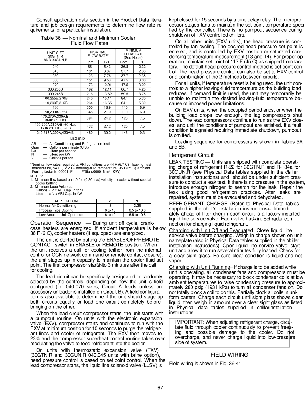
Table 36 — Nominal and Minimum Cooler
Fluid Flow Rates
UNIT SIZE | | NOMINAL | MINIMUM |
| FLOW RATE |
30GTN,R | | FLOW RATE* |
| (See Notes) |
AND 30GUN,R | | | |
| Gpm | L/s | Gpm | L/s |
| |
040 | | 86 | 5.43 | 36.8 | 2.32 |
045 | | 101 | 6.37 | 37.7 | 2.38 |
050 | | 123 | 7.76 | 37.7 | 2.38 |
060 | | 151 | 9.53 | 47.5 | 3.00 |
070 | | 173 | 10.91 | 47.5 | 3.00 |
080,230B | | 192 | 12.11 | 66.7 | 4.20 |
090,245B | | 216 | 13.62 | 59.5 | 3.75 |
100,255B,270B | | 240 | 15.14 | 84.1 | 5.30 |
110,290B,315B | | 264 | 16.65 | 84.1 | 5.30 |
130 | | 300 | 18.9 | 110 | 6.9 |
150,230A-255A | | 348 | 21.9 | 110 | 6.9 |
170,270A,330A/B, | | 384 | 24.2 | 120 | 7.5 |
360B (50 Hz) | |
| | | | |
190,290A,360A/B (60 Hz), | | 432 | 27.2 | 120 | 7.5 |
360A (50 Hz), 390B | |
| | | | |
210,315A,390A,420A/B | | 480 | 30.2 | 148 | 9.3 |
LEGEND | | | | |
ARI — Air Conditioning and Refrigeration Institute
Gpm — Gallons per minute (U.S.)
L/s — Liters per second
N— Liters per kW
V — Gallons per ton
*Nominal flow rates required at ARI conditions are 44 F (6.7 C) leaving-fluid temperature, 54 F (12.2 C) entering-fluid temperature, 95 F(35 C) ambient. Fouling factor is .00001 ft2 ⋅ hr ⋅ F/Btu (.000018 m2 ⋅ K/W).
NOTES:
1.Minimum flow based on 1.0 fps (0.30 m/s) velocity in cooler without special cooler baffling.
2.Minimum Loop Volumes:
Gallons = V x ARI Cap. in tons
Liters = N x ARI Cap. in kW
APPLICATION | V | N |
Normal Air Conditioning | 3 | 3.25 |
Process Type Cooling | 6 to 10 | 6.5 to 10.8 |
Low Ambient Unit Operation | 6 to 10 | 6.5 to 10.8 |
Operation Sequence — During unit off cycle, crank- case heaters are energized. If ambient temperature is below 36 F (2 C), cooler heaters (if equipped) are energized.
The unit is started by putting the ENABLE/OFF/REMOTE CONTACT switch in ENABLE or REMOTE position. When the unit receives a call for cooling (either from the internal control or CCN network command or remote contact closure), the unit stages up in capacity to maintain the cooler fluid set point. The first compressor starts 11/2 to 3 minutes after the call for cooling.
The lead circuit can be specifically designated or randomly selected by the controls, depending on how the unit is field configured (for 040-070 sizes, Circuit A leads unless an accessory unloader is installed on Circuit B). A field configura- tion is also available to determine if the unit should stage up both circuits equally or load one circuit completely before bringing on the other.
When the lead circuit compressor starts, the unit starts with a pumpout routine. On units with the electronic expansion valve (EXV), compressor starts and continues to run with the EXV at minimum position for 10 seconds to purge the refriger- ant lines and cooler of refrigerant. The EXV then moves to 23% and the compressor superheat control routine takes over, modulating the valve to feed refrigerant into the cooler.
On units with thermostatic expansion valve (TXV) (30GTN,R and 30GUN,R 040,045 units with brine option), head pressure control is based on set point control. When the lead compressor starts, the liquid line solenoid valve (LLSV) is
kept closed for 15 seconds by a time delay relay. The micropro- cessor stages fans to maintain the set point temperature speci- fied by the controller. There is no pumpout sequence during shutdown of TXV controlled chillers.
On all other units (EXV units), the head pressure is con- trolled by fan cycling. The desired head pressure set point is entered, and is controlled by EXV position or saturated con- densing temperature measurement (T3 and T4). For proper op- eration, maintain set point of 113 F (45 C) as shipped from fac- tory. The default head pressure control method is set point con- trol. The head pressure control can also be set to EXV control or a combination of the 2 methods between circuits.
For all units, if temperature reset is being used, the unit con- trols to a higher leaving-fluid temperature as the building load reduces. If demand limit is used, the unit may temporarily be unable to maintain the desired leaving-fluid temperature be- cause of imposed power limitations.
On EXV units, when the occupied period ends, or when the building load drops low enough, the lag compressors shut down. The lead compressors continue to run as the EXV clos- es, and until the conditions of pumpout are satisfied. If a fault condition is signaled requiring immediate shutdown, pumpout is omitted.
Loading sequence for compressors is shown in Tables 5A and 5B.
Refrigerant Circuit
LEAK TESTING — Units are shipped with complete operat- ing charge of refrigerant R-22 for 30GTN,R and R-134a for 30GUN,R (see Physical Data tables supplied in the chiller’s installation instructions) and should be under sufficient pres- sure to conduct a leak test. If there is no pressure in the system, introduce enough nitrogen to search for the leak. Repair the leak using good refrigeration practices. After leaks are repaired, system must be evacuated and dehydrated.
REFRIGERANT CHARGE (Refer to Physical Data tables supplied in the chiller’s installation instructions) — Immedi- ately ahead of filter drier in each circuit is a factory-installed liquid line service valve. Each valve has a 1/4-in. Schrader con- nection for charging liquid refrigerant.
Charging with Unit Off and Evacuated — Close liquid line service valve before charging. Weigh in charge shown on unit nameplate (also in Physical Data tables supplied in the chiller’s installation instructions). Open liquid line service valve; start unit and allow it to run several minutes fully loaded. Check for a clear sight glass. Be sure clear condition is liquid and not vapor.
Charging with Unit Running — If charge is to be added while unit is operating, all condenser fans and compressors must be operating. It may be necessary to block condenser coils at low ambient temperatures to raise condensing pressure to approxi- mately 280 psig (1931 kPa) to turn all condenser fans on. Do not totally block a coil to do this. Partially block all coils in uni- form pattern. Charge each circuit until sight glass shows clear liquid, then weigh in amount over a clear sight glass as listed in Physical data tables supplied in chiller’s installation instructions.
IMPORTANT: When adjusting refrigerant charge, circu- late fluid through cooler continuously to prevent freez- ing and possible damage to the cooler. Do not overcharge, and never charge liquid into low-pressure side of system.
FIELD WIRING
Field wiring is shown in Fig. 36-41.