Marquee Display Usage (See Fig. 19 and Tables 7-25) — The Marquee display module provides the
user interface to the ComfortLink™ control system. The dis-
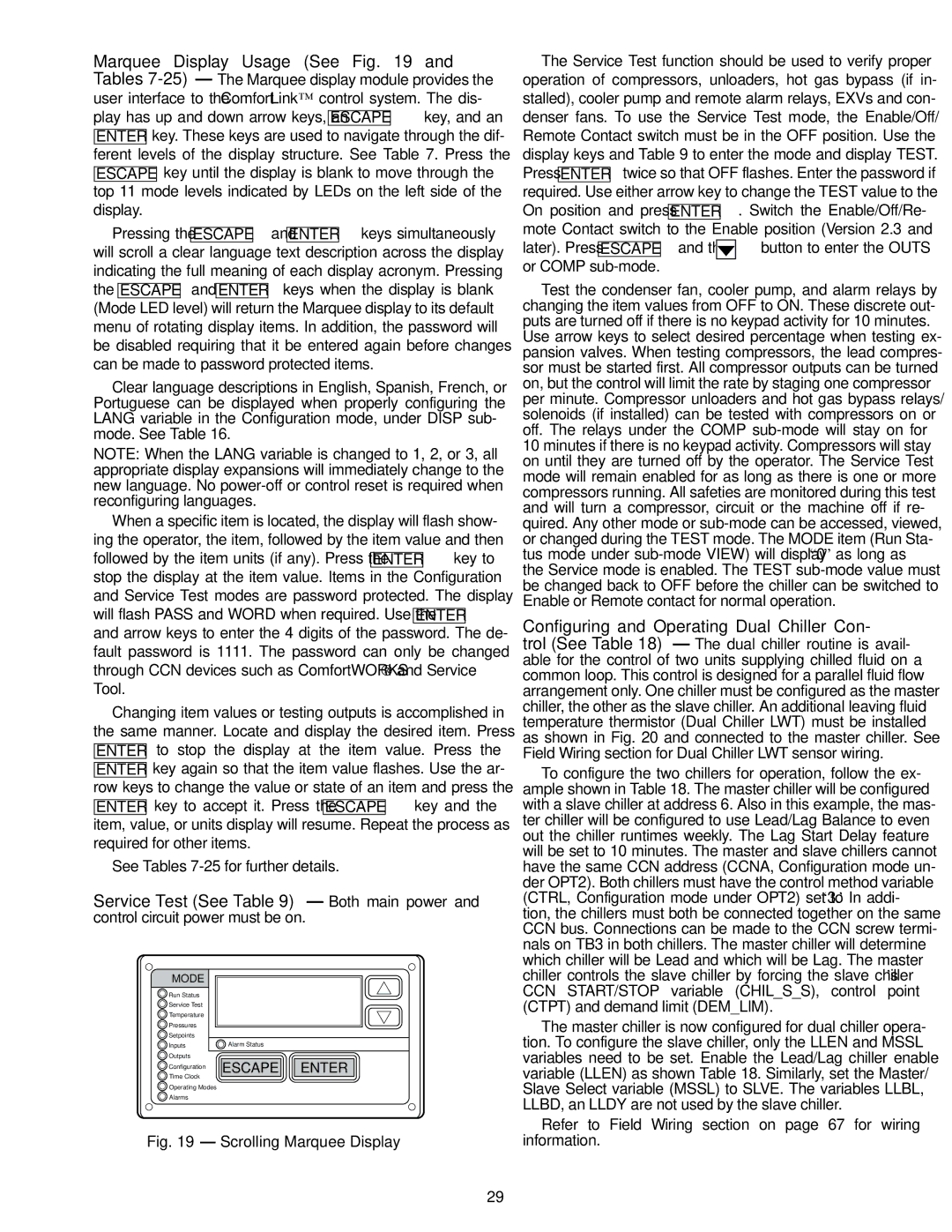
play has up and down arrow keys, an ESCAPE key, and an ENTER key. These keys are used to navigate through the dif- ferent levels of the display structure. See Table 7. Press the
ESCAPE key until the display is blank to move through the top 11 mode levels indicated by LEDs on the left side of the display.
Pressing the ESCAPE and ENTER keys simultaneously will scroll a clear language text description across the display indicating the full meaning of each display acronym. Pressing the ESCAPE and ENTER keys when the display is blank (Mode LED level) will return the Marquee display to its default menu of rotating display items. In addition, the password will be disabled requiring that it be entered again before changes can be made to password protected items.
Clear language descriptions in English, Spanish, French, or Portuguese can be displayed when properly configuring the LANG variable in the Configuration mode, under DISP sub- mode. See Table 16.
NOTE: When the LANG variable is changed to 1, 2, or 3, all appropriate display expansions will immediately change to the new language. No power-off or control reset is required when reconfiguring languages.
When a specific item is located, the display will flash show- ing the operator, the item, followed by the item value and then followed by the item units (if any). Press the ENTER key to stop the display at the item value. Items in the Configuration and Service Test modes are password protected. The display will flash PASS and WORD when required. Use the ENTER and arrow keys to enter the 4 digits of the password. The de- fault password is 1111. The password can only be changed through CCN devices such as ComfortWORKS® and Service Tool.
Changing item values or testing outputs is accomplished in the same manner. Locate and display the desired item. Press ENTER to stop the display at the item value. Press the ENTER key again so that the item value flashes. Use the ar- row keys to change the value or state of an item and press the ENTER key to accept it. Press the ESCAPE key and the item, value, or units display will resume. Repeat the process as required for other items.
See Tables 7-25 for further details.
Service Test (See Table 9) — Both main power and
control circuit power must be on.
MODE | |
Run Status | |
Service Test | |
Temperature | |
Pressures | |
Setpoints | |
Inputs | Alarm Status |
Outputs | ESCAPE ENTER |
Configuration |
Time Clock | |
Operating Modes | |
Alarms | |
Fig. 19 — Scrolling Marquee Display
The Service Test function should be used to verify proper operation of compressors, unloaders, hot gas bypass (if in- stalled), cooler pump and remote alarm relays, EXVs and con- denser fans. To use the Service Test mode, the Enable/Off/ Remote Contact switch must be in the OFF position. Use the display keys and Table 9 to enter the mode and display TEST.
Press ENTER twice so that OFF flashes. Enter the password if
required. Use either arrow key to change the TEST value to the
On position and press ENTER . Switch the Enable/Off/Re-
mote Contact switch to the Enable position (Version 2.3 and
later). Press ESCAPE and the 

 button to enter the OUTS or COMP sub-mode.
Test the condenser fan, cooler pump, and alarm relays by changing the item values from OFF to ON. These discrete out- puts are turned off if there is no keypad activity for 10 minutes. Use arrow keys to select desired percentage when testing ex- pansion valves. When testing compressors, the lead compres- sor must be started first. All compressor outputs can be turned on, but the control will limit the rate by staging one compressor per minute. Compressor unloaders and hot gas bypass relays/ solenoids (if installed) can be tested with compressors on or off. The relays under the COMP sub-mode will stay on for 10 minutes if there is no keypad activity. Compressors will stay on until they are turned off by the operator. The Service Test mode will remain enabled for as long as there is one or more compressors running. All safeties are monitored during this test and will turn a compressor, circuit or the machine off if re- quired. Any other mode or sub-mode can be accessed, viewed, or changed during the TEST mode. The MODE item (Run Sta- tus mode under sub-mode VIEW) will display “0” as long as the Service mode is enabled. The TEST sub-mode value must be changed back to OFF before the chiller can be switched to Enable or Remote contact for normal operation.
Configuring and Operating Dual Chiller Con- trol (See Table 18) — The dual chiller routine is avail- able for the control of two units supplying chilled fluid on a common loop. This control is designed for a parallel fluid flow arrangement only. One chiller must be configured as the master chiller, the other as the slave chiller. An additional leaving fluid temperature thermistor (Dual Chiller LWT) must be installed as shown in Fig. 20 and connected to the master chiller. See Field Wiring section for Dual Chiller LWT sensor wiring.
To configure the two chillers for operation, follow the ex- ample shown in Table 18. The master chiller will be configured with a slave chiller at address 6. Also in this example, the mas- ter chiller will be configured to use Lead/Lag Balance to even out the chiller runtimes weekly. The Lag Start Delay feature will be set to 10 minutes. The master and slave chillers cannot have the same CCN address (CCNA, Configuration mode un- der OPT2). Both chillers must have the control method variable (CTRL, Configuration mode under OPT2) set to ‘3.’ In addi- tion, the chillers must both be connected together on the same CCN bus. Connections can be made to the CCN screw termi- nals on TB3 in both chillers. The master chiller will determine which chiller will be Lead and which will be Lag. The master chiller controls the slave chiller by forcing the slave chiller’s CCN START/STOP variable (CHIL_S_S), control point (CTPT) and demand limit (DEM_LIM).
The master chiller is now configured for dual chiller opera- tion. To configure the slave chiller, only the LLEN and MSSL variables need to be set. Enable the Lead/Lag chiller enable variable (LLEN) as shown Table 18. Similarly, set the Master/ Slave Select variable (MSSL) to SLVE. The variables LLBL, LLBD, an LLDY are not used by the slave chiller.
Refer to Field Wiring section on page 67 for wiring information.