Safety Devices — Chillers contain many safety devices and protection logic built into electronic control. Following is a brief summary of major safeties.
COMPRESSOR PROTECTION
Circuit Breaker — One manual-reset, calibrated-trip magnetic circuit breaker for each compressor protects against overcur- rent. Do not bypass or increase size of a breaker to correct problems. Determine cause for trouble and correct before resetting breaker. Circuit breaker must-trip amps (MTA) are listed on individual circuit breakers, and on unit label diagrams.
30GTN,R and 30GUN,R070 (50 Hz), 080-110 and 230B- 315B Compressor Protection Board (CPCS) — The CPCS is used to control and protect compressors and crankcase heaters. Board provides following features:
•compressor contactor control
•crankcase heater control
•ground current protection
•status communication to processor board
•high-pressure protection
One large relay is located on CPCS that controls crankcase heater and compressor contactor. In addition, this relay pro- vides a set of contacts that the microprocessor monitors to de- termine operating status of compressor. If the MBB determines that compressor is not operating properly through signal con- tacts, control locks compressor off.
The CPCS contains logic that can detect if current-to- ground of any winding exceeds 2.5 amps; if so, compressor shuts down.
A high-pressure switch with a trip pressure of 426 ± 7 psig (2936 ± 48 kPa) is mounted on each compressor; switch setting is shown in Table 34. Switch is wired in series with the CPCS. If switch opens, CPCS relay opens, processor detects it through signal contacts, and compressor locks off. A loss-of-charge switch is also wired in series with the high-pressure switch and CPCS.
If any of these switches opens during operation, the com- pressor stops and the failure is detected by the MBB when sig- nal contacts open. If lead compressor in either circuit is shut down by high-pressure switch, ground current protector, loss of charge switch, or oil pressure switch, all compressors in the cir- cuit are locked off.
30GTN,R and 30GUN,R 130-210,230A-315A and 330A/B-420A/B — A control relay in conjunction with a ground fault module replaces the function of the CPCS (above). To reset, press the push-button switch (near the Mar- quee display).
Table 34 — Pressure Switch Settings,
psig (kPa)
SWITCH | CUTOUT | CUT-IN |
High Pressure | 426 | ± 7 | 320 | ± 20 |
30GTN,R Units | (2936 | ± 48) | (2205 | ± 138) |
High Pressure | 280 ± 10 | 180 | ± 20 |
30GUN,R Units | (1830 | ± 69) | (1240 | ± 138) |
Loss-of-Charge | 7 (48.2) | 22 (151.6) |
LOW OIL PRESSURE PROTECTION — Lead | compres- |
sor in each circuit is equipped with a switch to detect low oil pressure. Switch is connected directly to processor board. Switch is set to open at approximately 5 psig (35 kPa) and to close at 9 psig (62 kPa) maximum. If switch opens when compressor is running, CR or processor board stops all com- pressors in circuit. During start-up, switch is bypassed for 2 minutes.
CRANKCASE HEATERS — Each compressor has a 180-w crankcase heater to prevent absorption of liquid refrigerant by oil in crankcase when compressor is not running. Heater power
source is auxiliary control power, independent of main unit power. This assures compressor protection even when main unit power disconnect switch is off.
IMPORTANT: Never open any switch or disconnect that deenergizes crankcase heaters unless unit is being serviced or is to be shut down for a prolonged period. After a prolonged shutdown or service, energize crank- case heaters for 24 hours before starting unit.
COOLER PROTECTION
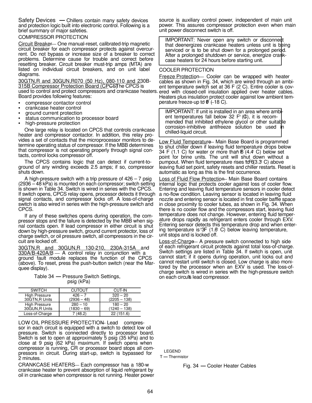
Freeze Protection — Cooler can be wrapped with heater cables as shown in Fig. 34, which are wired through an ambi- ent temperature switch set at 36 F (2 C). Entire cooler is cov- ered with closed-cell insulation applied over heater cables. Heaters plus insulation protect cooler against low ambient tem- perature freeze-up to 0° F (–18 C).
IMPORTANT: If unit is installed in an area where ambi- ent temperatures fall below 32 F (0° C), it is recom- mended that inhibited ethylene glycol or other suitable corrosion-inhibitive antifreeze solution be used in chilled-liquid circuit.
Low Fluid Temperature — Main Base Board is programmed to shut chiller down if leaving fluid temperature drops below 34 F (1.1 C) for water or more than 8° F (4.4° C) below set point for brine units. The unit will shut down without a pumpout. When fluid temperature rises to 6° F (3.3° C) above leaving fluid set point, safety resets and chiller restarts. Reset is automatic as long as this is the first occurrence.
Loss of Fluid Flow Protection — Main Base Board contains internal logic that protects cooler against loss of cooler flow. Entering and leaving fluid temperature sensors in cooler detect a no-flow condition. Leaving sensor is located in leaving fluid nozzle and entering sensor is located in first cooler baffle space in close proximity to cooler tubes, as shown in Fig. 34. When there is no cooler flow and the compressors start, leaving fluid temperature does not change. However, entering fluid temper- ature drops rapidly as refrigerant enters cooler through EXV. Entering sensor detects this temperature drop and when enter- ing temperature is 3° F (1.6° C) below leaving temperature, unit stops and is locked off.
Loss-of-Charge — A pressure switch connected to high side of each refrigerant circuit protects against total loss-of-charge. Switch settings are listed in Table 34. If switch is open, unit cannot start; if it opens during operation, unit locks out and cannot restart until switch is closed. Low charge is also moni- tored by the processor when an EXV is used. The loss-of- charge switch is wired in series with the high-pressure switch on each circuit’s lead compressor.
LEGEND
T — Thermistor
Fig. 34 — Cooler Heater Cables