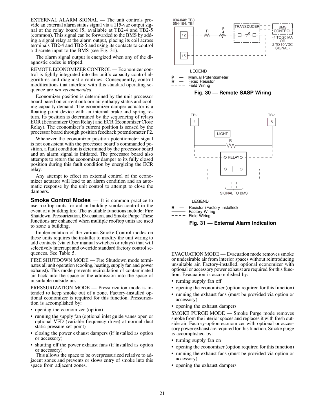
EXTERNAL ALARM SIGNAL Ð The unit controls pro- vide an external alarm status signal via a
The alarm signal output is energized when any of the di- agnostic codes is tripped.
R
12
15
P
TRANSDUCER
BMS
CONTROL
(4 TO 20 MA
OR
2 TO 10 VDC
SIGNAL)
REMOTE ECONOMIZER CONTROL Ð Economizer con- trol is tightly integrated into the unit's capacity control al- gorithms and diagnostic routines. Consequently, control modi®cations that interfere with this standard operating se- quence are not recommended.
Economizer position is determined by the unit processor board based on current outdoor air enthalpy status and cool- ing capacity demand. The economizer damper actuator is a ¯oating point device with an internal brake and spring re- turn. Its position is determined by the sequencing of relays EOR (Economizer Open Relay) and ECR (Economizer Close Relay). The economizer's current position is sensed by the processor board through position feedback potentiometer P2.
Whenever the economizer position potentiometer signal is not consistent with the processor board's commanded po- sition, a fault condition is determined by the processor board and an alarm signal is initiated. The processor board also attempts to return the economizer damper to its fully closed position during this fault condition by energizing the ECR relay.
Any attempt to effect an external control of the econo- mizer actuator will lead to an alarm condition and an auto- matic response by the unit control to attempt to close the dampers.
Smoke Control Modes Ð It is common practice to use rooftop units for aid in building smoke control in the event of a building ®re. The available functions include: Fire Shutdown, Pressurization, Evacuation, and Smoke Purge. These functions are enhanced when multiple rooftop units are used to zone a building.
Implementation of the various Smoke Control modes on these units requires the installer to modify the unit wiring to add contacts (via either manual switches or relays) that will selectively interrupt and override standard factory control se- quences. See Table 5.
FIRE SHUTDOWN MODE Ð Fire Shutdown mode termi- nates all unit operation (cooling, heating, supply fan and power exhaust). This mode prevents recirculation of contaminated air back into the space or the admission into the space of unsuitable outside air.
PRESSURIZATION MODE Ð Pressurization mode is in- tended to keep smoke out of a zone.
·opening the economizer (option)
·running the supply fan (optional inlet guide vanes open or optional VFD (variable frequency drive) at normal duct static pressure set point)
·closing the power exhaust dampers (if installed as option or accessory)
·shutting off the power exhaust fans (if installed as option or accessory)
This allows the space to be overpressurized relative to ad- jacent zones and prevents or slows entry of smoke into this space from adjacent zones.
LEGEND
PÐ Manual Potentiometer R Ð Fixed Resistor
Field Wiring
Fig. 30 Ð Remote SASP Wiring
TB2 | TB2 |
4 | 5 |
| LIGHT |
| R |
| RELAY |
SIGNAL TO BMS
LEGEND
RÐ Resistor (Factory Installed) Factory Wiring
Field Wiring
Fig. 31 Ð External Alarm Indication
EVACUATION MODE Ð Evacuation mode removes smoke or undesirable air from interior spaces without reintroducing unsuitable air.
·turning supply fan off
·opening the economizer (option required for this function)
·running the exhaust fans (must be provided via option or accessory)
·opening the exhaust dampers
SMOKE PURGE MODE Ð Smoke Purge mode removes smoke from the interior spaces and replaces it with fresh out- side air.
·turning supply fan on
·opening the economizer (option required for this function)
·running the exhaust fans (must be provided via option or accessory)
·opening the exhaust dampers
21
