48FK,JK034-074 50FK,FY,JK,JY034-104 Variable-Air Volume Rooftop Units
Controls Operation and Troubleshooting
SAFETY CONSIDERATIONS
CONTENTS cont
GENERAL
Return-Air Temperature
Table 1 Ð Pin Terminal Connector J1 Thermistor Inputs
Fig. 1 Ð Processor Board
Table 2 Ð Pin Terminal Connector J2 Status Switch Inputs
Fig. 3 Ð Pin Terminal Connector J2
Status Switch Inputs
Fig. 2 Ð Pin Terminal Connector J1 Thermistor Inputs
The potentiometer locations and functions are as follows
Fig. 5 Ð Relay Board
Table 3 Ð Output Pin and Terminal Assignments
Compressor Operation
48FK,JK ONLY
Fig. 8 Ð Thermistor T1 Location, 50FK,JK034-048 Units
GAS SECTION
HORIZONTAL SUPPLY SECTION
GAS SECTION
Fig. 9 Ð Thermistor T1 Location, 48FK,JK, 50JY and
50JKX,JKY 054-074 Units and 50FKX,FKY and 50FY054-104 Units
Fig. 10 Ð Thermistor T1 Location, 50FK,JK054-074 Units
STANDARD
Fig. 11 Ð Thermistor T2 Location, Size 034-048 Units
Fig. 12 Ð Thermistor T2 Location, Size 054-104 Units
Fig. 13 Ð Thermistor T3 and T4 Locations Size 034-048 Units
054 UNITS 064, 074, 078 UNITS 088, 104 UNITS
Fig. 14 Ð Thermistor T3 and T4 Locations, Size 054-104 Units
Fig. 18 Ð Variable Frequency Drive Sizes 034-048 and
Fig. 15 Ð Accessory Relay Board Standard Factory Supplied
Fig. 16 Ð Two-Step Demand Limit Module
Fig. 17 Ð Enthalpy Sensor Location
Space Temperature Reset
CONTROLS INSTALLATION
Fig. 20 Ð Unit Control Box Arrangement, Sizes
Fig. 21 Ð Unit Control Box Arrangement, Sizes
Fig. 22 Ð Unit Control Box Arrangement, Sizes 088 and
Fig. 24 Ð Heat Interlock Relay
Fig. 23 Ð Occupied/Unoccupied Switch with Night Setback Thermostat
Fig. 25 Ð Accessory Reset Board
Voltage Drop Characteristics
Fig. 26 Ð Space Temperature Sensor Averaging
2-Step Demand Limit Control Module
Fig. 29 Ð 115-Volt Field Wiring to Accessory
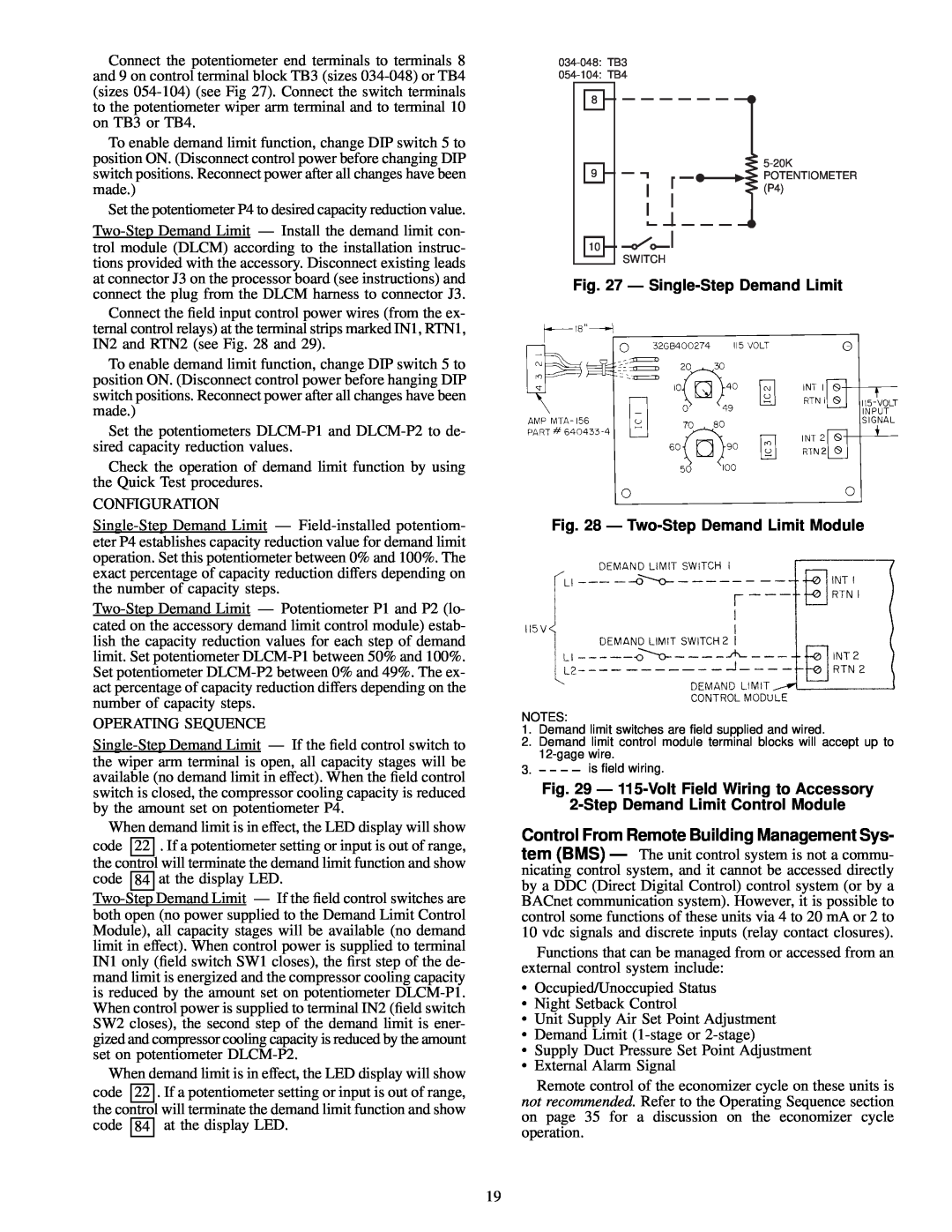
Fig. 27 Ð Single-Step Demand Limit
Fig. 28 Ð Two-Step Demand Limit Module
This emulation requires the following eld-supplied parts
R Ð Resistor Factory Installed Factory Wiring Field Wiring
Fig. 30 Ð Remote SASP Wiring
Fig. 31 Ð External Alarm Indication
P Ð Manual Potentiometer R Ð Fixed Resistor Field Wiring
Fire
Table 6 Ð Smoke Control Switches Required for Each Mode
Modulating Power
Table 5 Ð Smoke Control Modes
SIZE in
Table 7 Ð Switch Functions
Modulating Power Exhaust
Table 8 Ð Tubing Size
034-048 UNITS
Fig. 32 Ð Smoke Control Wiring
ALL UNITS
Fig. 35 Ð Modulating Power Exhaust Differential Pressure Switch Sizes
Fig. 33 Ð Modulating Power Exhaust and Inlet
Guide Vane Differential Pressure Switch Sizes
Pressure Switch and Variable Frequency Drive
Table 9 Ð Potentiometer Inputs and Ranges
Table 10 Ð Conguration Header and DIP Switch Factory Settings
Table 11 Ð Conguration Header Jumpers
Table 12 Ð DIP Switches
Size 078-104 Units
Fig. 36 Ð Inlet Guide Vane Motor 50FK,JK034-074 Units
Fig. 37 Ð Inlet Guide Vane Motor, 48FK,JK, 50FY,JY
and 50FJX,FJY,FKX,FKY034-074 Units Fig. 38 Ð Inlet Guide Vane Motor
Fig. 41 Ð Jumper Removal to Disable Motor
READ STOP WRITE RESET
Fig. 39 Ð Differential Pressure Switch for Inlet Guide
Modulating Power Exhaust Option
Table 13 Ð VFD Set Point Frequency Command for Duct Pressure
Modulating Power Exhaust Option or Acces
Table 14 Ð Changing the VFD Set Point Frequency Command
START UNIT
NORMAL
Table 15 Ð Quick Test, Unit Conguration and Switch Check
CONTROL SWITCH
QUICK
Table 17 Ð Quick Test, Output Relay Check
Table 16 Ð Quick Test, Thermistor and Potentiometer Check
Table 18 Ð Sensor Resistance Values
OPERATING INFORMATION
warm-up routine, and a 26 will be displayed
034 AND 038 UNITS
Fig. 42 Ð Component Arrangement, 034-048 Units
044 AND 048 UNITS
088, 104 UNITS 104 UNITS
Fig. 43 Ð Component Arrangement, 054-104 Units
054, 064 UNITS
074, 078 UNITS
Supply Fan Control with IGV Ð In most VAV units, the supply fan static pressure is controlled by inlet guide vanes. The inlet guide vanes operate independently from the micro- processor. The supply static pressure is controlled by a dif- ferential pressure switch. If the unit is equipped with a re- turn fan, building pressure is controlled by another differential pressure switch
Fig. 44 Ð Modulating Power Exhaust Component Locations Sizes
Fig. 45 Ð Modulating Power Exhaust Component Locations Sizes
Page
Table 19 Ð Compressor Loading and Unloading Sequences
Table 19 Ð Compressor Loading and Unloading Sequences cont
Table 20 Ð Controls Troubleshooting
TROUBLESHOOTING
Table 21 Ð Operation Status Codes
Table 22 Ð Diagnostic Codes
ergize alarm light and cause an error code of 83 to be dis
· Wiring Problem Ð If the circuit is open, a failure will be detected
82 to be displayed on display board when display button is
will be energized and an error code of 82 will be displayed
Page
Fig. 49 Ð Relay Board Test Points
Fig. 48 Ð Processor Board Test Points
Fig. 51 Ð Display Board Pin Terminal Connector J10
Fig. 50 Ð Relay Board Pin Terminal Connector J9
Table 23 Ð Voltage Reading
Step 2 Ð High-voltage relay resistance check
Table 24 Ð Pin Terminal Connector J1 Voltages
Table 25 Ð Pin Terminal Connector J2 Voltages
Step 1 Ð Low-voltage relay resistance check
Table 28 Ð Enthalpy Sensor Checkout
Table 27 Ð Terminal Strip J5 Connector Resistance Reading
1. Disconnect all power to the unit and the VFD
Fig. 52 Ð Damper Motor Connection Diagram VAV
Variable Frequency Drive
Gr.SF
Table 29 Ð Carrier Default Program Parameter Values
Frequency Settings
Gr.Fb
Fig. 54 Ð Variable Frequency Drive Terminal Block Size 054-104 Units
Table 30 Ð Required User Adjusted Defaults
Table 31 Ð Motor Overload Settings
Fig. 53 Ð Variable Frequency Drive Terminal Block Size 034-048 Units
LEGEND AND NOTES FOR FIG
Page
Page
CALL FOR FREE CATALOG
SERVICE TRAINING
I. PRE-START-UP
START-UP CHECKLIST
II. PRELIMINARY CHECKLIST ITEMS
CONTROL SETTINGS
ELECTRICAL
TEMPERATURES
III. START-UP
IV. NOTES