Controls Operation and Troubleshooting
48FK,JK034-074 50FK,FY,JK,JY034-104 Variable-Air Volume Rooftop Units
CONTENTS cont
SAFETY CONSIDERATIONS
GENERAL
Table 1 Ð Pin Terminal Connector J1 Thermistor Inputs
Return-Air Temperature
Fig. 1 Ð Processor Board
Fig. 2 Ð Pin Terminal Connector J1 Thermistor Inputs
Fig. 3 Ð Pin Terminal Connector J2
Status Switch Inputs
Table 2 Ð Pin Terminal Connector J2 Status Switch Inputs
The potentiometer locations and functions are as follows
Table 3 Ð Output Pin and Terminal Assignments
Fig. 5 Ð Relay Board
Compressor Operation
HORIZONTAL SUPPLY SECTION
Fig. 8 Ð Thermistor T1 Location, 50FK,JK034-048 Units
GAS SECTION
48FK,JK ONLY
Fig. 10 Ð Thermistor T1 Location, 50FK,JK054-074 Units
Fig. 9 Ð Thermistor T1 Location, 48FK,JK, 50JY and
50JKX,JKY 054-074 Units and 50FKX,FKY and 50FY054-104 Units
GAS SECTION
Fig. 13 Ð Thermistor T3 and T4 Locations Size 034-048 Units
Fig. 11 Ð Thermistor T2 Location, Size 034-048 Units
Fig. 12 Ð Thermistor T2 Location, Size 054-104 Units
STANDARD
Fig. 14 Ð Thermistor T3 and T4 Locations, Size 054-104 Units
054 UNITS 064, 074, 078 UNITS 088, 104 UNITS
Fig. 17 Ð Enthalpy Sensor Location
Fig. 15 Ð Accessory Relay Board Standard Factory Supplied
Fig. 16 Ð Two-Step Demand Limit Module
Fig. 18 Ð Variable Frequency Drive Sizes 034-048 and
CONTROLS INSTALLATION
Space Temperature Reset
Fig. 20 Ð Unit Control Box Arrangement, Sizes
Fig. 21 Ð Unit Control Box Arrangement, Sizes
Fig. 22 Ð Unit Control Box Arrangement, Sizes 088 and
Voltage Drop Characteristics
Fig. 23 Ð Occupied/Unoccupied Switch with Night Setback Thermostat
Fig. 25 Ð Accessory Reset Board
Fig. 24 Ð Heat Interlock Relay
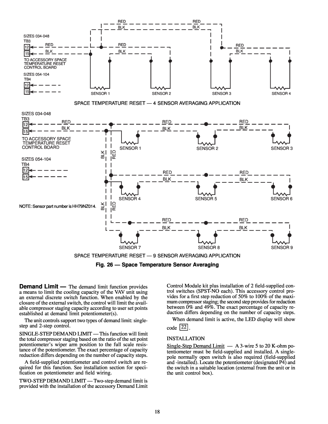
Fig. 26 Ð Space Temperature Sensor Averaging
Fig. 28 Ð Two-Step Demand Limit Module
Fig. 29 Ð 115-Volt Field Wiring to Accessory
Fig. 27 Ð Single-Step Demand Limit
2-Step Demand Limit Control Module
This emulation requires the following eld-supplied parts
P Ð Manual Potentiometer R Ð Fixed Resistor Field Wiring
Fig. 30 Ð Remote SASP Wiring
Fig. 31 Ð External Alarm Indication
R Ð Resistor Factory Installed Factory Wiring Field Wiring
Table 5 Ð Smoke Control Modes
Table 6 Ð Smoke Control Switches Required for Each Mode
Modulating Power
Fire
Table 8 Ð Tubing Size
Table 7 Ð Switch Functions
Modulating Power Exhaust
SIZE in
Fig. 32 Ð Smoke Control Wiring
034-048 UNITS
ALL UNITS
Pressure Switch and Variable Frequency Drive
Fig. 33 Ð Modulating Power Exhaust and Inlet
Guide Vane Differential Pressure Switch Sizes
Fig. 35 Ð Modulating Power Exhaust Differential Pressure Switch Sizes
Table 10 Ð Conguration Header and DIP Switch Factory Settings
Table 9 Ð Potentiometer Inputs and Ranges
Table 11 Ð Conguration Header Jumpers
Table 12 Ð DIP Switches
and 50FJX,FJY,FKX,FKY034-074 Units Fig. 38 Ð Inlet Guide Vane Motor
Fig. 36 Ð Inlet Guide Vane Motor 50FK,JK034-074 Units
Fig. 37 Ð Inlet Guide Vane Motor, 48FK,JK, 50FY,JY
Size 078-104 Units
Modulating Power Exhaust Option
READ STOP WRITE RESET
Fig. 39 Ð Differential Pressure Switch for Inlet Guide
Fig. 41 Ð Jumper Removal to Disable Motor
Modulating Power Exhaust Option or Acces
Table 13 Ð VFD Set Point Frequency Command for Duct Pressure
Table 14 Ð Changing the VFD Set Point Frequency Command
START UNIT
QUICK
Table 15 Ð Quick Test, Unit Conguration and Switch Check
CONTROL SWITCH
NORMAL
Table 16 Ð Quick Test, Thermistor and Potentiometer Check
Table 17 Ð Quick Test, Output Relay Check
OPERATING INFORMATION
Table 18 Ð Sensor Resistance Values
warm-up routine, and a 26 will be displayed
Fig. 42 Ð Component Arrangement, 034-048 Units
034 AND 038 UNITS
044 AND 048 UNITS
074, 078 UNITS
Fig. 43 Ð Component Arrangement, 054-104 Units
054, 064 UNITS
088, 104 UNITS 104 UNITS
Supply Fan Control with IGV Ð In most VAV units, the supply fan static pressure is controlled by inlet guide vanes. The inlet guide vanes operate independently from the micro- processor. The supply static pressure is controlled by a dif- ferential pressure switch. If the unit is equipped with a re- turn fan, building pressure is controlled by another differential pressure switch
Fig. 44 Ð Modulating Power Exhaust Component Locations Sizes
Fig. 45 Ð Modulating Power Exhaust Component Locations Sizes
Page
Table 19 Ð Compressor Loading and Unloading Sequences
Table 19 Ð Compressor Loading and Unloading Sequences cont
TROUBLESHOOTING
Table 20 Ð Controls Troubleshooting
Table 21 Ð Operation Status Codes
Table 22 Ð Diagnostic Codes
will be energized and an error code of 82 will be displayed
· Wiring Problem Ð If the circuit is open, a failure will be detected
82 to be displayed on display board when display button is
ergize alarm light and cause an error code of 83 to be dis
Page
Fig. 48 Ð Processor Board Test Points
Fig. 49 Ð Relay Board Test Points
Fig. 50 Ð Relay Board Pin Terminal Connector J9
Fig. 51 Ð Display Board Pin Terminal Connector J10
Table 23 Ð Voltage Reading
Step 1 Ð Low-voltage relay resistance check
Table 24 Ð Pin Terminal Connector J1 Voltages
Table 25 Ð Pin Terminal Connector J2 Voltages
Step 2 Ð High-voltage relay resistance check
Table 27 Ð Terminal Strip J5 Connector Resistance Reading
Table 28 Ð Enthalpy Sensor Checkout
Fig. 52 Ð Damper Motor Connection Diagram VAV
1. Disconnect all power to the unit and the VFD
Variable Frequency Drive
Gr.Fb
Table 29 Ð Carrier Default Program Parameter Values
Frequency Settings
Gr.SF
Fig. 53 Ð Variable Frequency Drive Terminal Block Size 034-048 Units
Table 30 Ð Required User Adjusted Defaults
Table 31 Ð Motor Overload Settings
Fig. 54 Ð Variable Frequency Drive Terminal Block Size 054-104 Units
LEGEND AND NOTES FOR FIG
Page
Page
SERVICE TRAINING
CALL FOR FREE CATALOG
CONTROL SETTINGS
START-UP CHECKLIST
II. PRELIMINARY CHECKLIST ITEMS
I. PRE-START-UP
IV. NOTES
TEMPERATURES
III. START-UP
ELECTRICAL